Laser Light Replacement
Prerequisites
Overview
Procedures for replacing alignment lights, and alignment of the laser lights. There is one (1) laser light in the top middle assembly.
1 Laser Light Removal
Procedure
- Perform Lock Out / Tag Out Process (refer to Lockout / Tagout for System Cabinet PDU Main Breaker.).
- Remove the center control panel to allow access to power supply connector. Refer to Magnet Enclosure Control Panels.
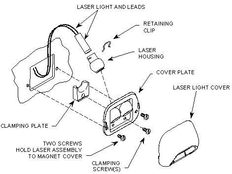
- Pry cover off of defective laser assembly with a screwdriver. See Figure 1.
- Remove two screws, and let laser light assembly hang free. See Figure 1.
- Remove screw clamping laser in place. See Figure 1.
- Using a needle nose pliers, pull retaining clip off laser/housing assembly. See Figure 1.
- Slide laser light out of housing. See Figure 1.
Figure 1. LASER ALIGNMENT LIGHT ASSEMBLY
- Follow laser light leads to the power supply connector and pull connector off.
2 Laser Light Replacement
Procedure
- Plug new laser light into power supply board.
- Slide housing onto laser and install retaining clip. See Figure 1.
- Install clamp and slotted screw onto cover plate. See Figure 1.
- Install cover plate to magnet front end bell using two furnished screws. See Figure 1.
- Reinstall the center control panel.
- Refer to the corresponding Lockout/Tagout power restoration process.
- Turn on laser alignment lights and check alignment of replaced laser. Refer to Laser Light Alignment for procedure on how to properly align the laser lights.
3 Finalization
Procedure
- Perform any scan to obtain the coronal image. Check that the phantom image is at the center of display.
- Perform DQA II Tool to adjust Iso-Center Z.
- Perform Signal to Noise - Head Scan.