Magnet Enclosure Control Panels
Prerequisites
Procedures for replacing operator control/display hardware in the front magnet enclosure. There are three (3) control panels on the front cover. The three control panels can be removed independently.
Procedure
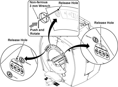
- Insert non ferrous 3mm L-wrench to release hole of panel.note:
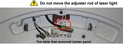
When removing center panel, do not touch adjuster rod of laser light. If you moved adjuster rod, check or adjust the laser light position after replacement.
Figure 1. Laser Light Adjuster of Center Panel
- Push and rotate non ferrous 3mm L-wrench. The panel lock will
be released.note:
The control panel is connected to connector with behind side.
Figure 2.
- For center panel, remove the panel and disconnect the 5 connectors.
For R/L panel, remove the panel and disconnect one connector.
Figure 3. Removing Control Panels
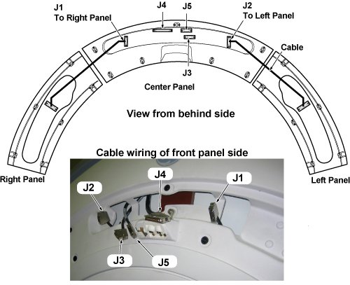
Figure 4. Connection Locations
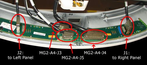
- Once the panels are free from the enclosure, detach all the cables from each Control Panel.
- Installation is reverse order of removal.
Finalization
- Restore Power. Refer to System Cabinet PDU Main Breaker LOTO Procedure.
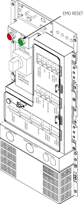
- The J4 connector provides communications for the Emergency Stop.
Press the EMO Reset button on the PDU of system
cabinet after the power has been returned to the system.
Figure 5. EMO Reset on the PDU
- Perform Magnet Enclosure Button Test.
- Perform Signal to Noise - Head Scan.