Equipment Setup and Prescan Checks
Prerequisites
Grafidy 3 will take 3 hours if running a full procedure on a BRM and 6 hours if running the full procedure on a TwinSpeed doing WHOLE and ZOOM.
1 Set Up Grafidy Kit for First Axis Calibration
Procedure
- Remove the Head Coil and holder from the cradle.
- Select the coils from the kit that matches the system type.
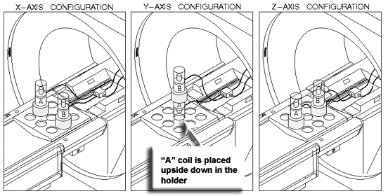
- Place the coil baseplate on the cradle, and configure the Grafidy
coil/samples and collars appropriately for the first axis on which
Grafidy will be performed. (See the Figure 1.)
Figure 1. Grafidy Phantom Configurations
 note:
note:In the X and Z configurations, the coil/sample is placed with the sample at the top. In the Y configuration, the top coil/sample is placed with the sample on top, while the lower coil/sample is inverted so that the sample is on the bottom. Also in the Y configuration, no collars are used beneath the bottom sample.
To complete Step 4 through Step 10, refer to for Figure 2.
Figure 2. Grafidy Kit Setup
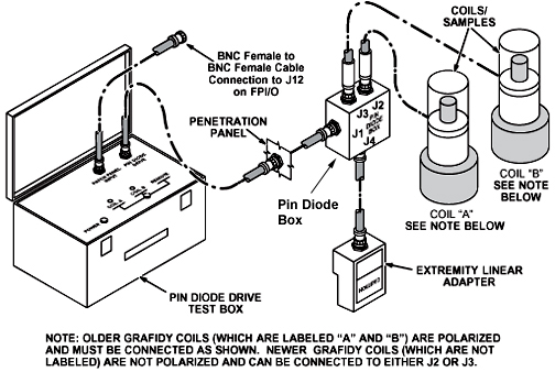
- Plug the Extremity/Linear Adapter into the Quad Head Coil Carriage
Assembly, and connect a two-foot coaxial cable from Extremity/Linear
Adapter BNC to J4 on the Pin Diode Box.note:
There are multiple lengths of cable used for this portion of the procedure. The short cable is the two-foot cable, the medium length cable is either an eight-foot or five-foot, and the long cable is any cable length that will accommodate the long cable runs: 90-foot cable, a combination of 30-foot cables, or a custom cable that you may have created.
- Connect the long coaxial cable from J1 on the Pin Diode Box
to a service coaxial feed-through on the Penetration Panel (Exam Room
side).
- Route the cable through the bore of the magnet, exiting at the rear.
- Connect the other end of the cable to the Pin Diode Drive Test
Box. (See Figure 2.)note:
It is not necessary to use a 90-foot cable. This length is usually supplied in some Grafidy kits; other kits are supplied with three 30-foot cables. Use the length of cable that best suits the site.
- Landmark on the centerline of the Grafidy coil baseplate, not the coils. On the front of the magnet enclosure, press LANDMARK and MOVE TO SCAN on the keypad.
- Verify that the switch on the Pin Diode Drive Test Box is in the Remote position.
- Connect a BNC cable from the TRIGGER INPUT (called PATCH PANEL INPUT on some older boxes) connector on the Pin Diode Drive Test Box to J12 (DAB out 6) on the FP I/O Board on the front of the RRF chassis.
- Plug in the power cord for the Pin Diode Drive Test Box.
- Place the power switch for the Pin Diode Drive Test Box in the
On position (referred to as 1).
-
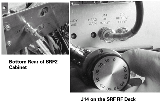
RFS Cabinets: Install a rotary step attenuator set to 20 dB in series with the cable connected to J14 (RF Input) on the back of the RF Amplifier.
-
RF/PDU (SRFD), SRF and SRF2 Cabinets: Install a rotary step attenuator set to 20 dB between J1 on the rear of the System Cabinet (exciter output) by disconnecting the cable at J1 on the back of the RF Cabinet and installing the attenuator between the cable and J1.
note:An alternative is to use J14 on the fiber optic bracket at the rear of the RF Amplifier. (See Figure 3.)
Figure 3. SRF and SRF2 Attenuator Points
-
RF/PDU (SRFD): Although envelope feedback is not employed on the RF/PDU Cabinet, attenuation is still required. Install a rotary step attenuator set to 20 dB in series with the cable connected to J14 RF INPUT on the front of the RFI module.
-
2 Prescan Checks
Procedure
- Center the laser crosshairs on top of the coils and landmark the system, and Advance to Scan to 0 mm.
- Begin a new patient scan and enter geservice as the Patient ID.
- Enter a Patient Weight of 111 lbs.
- Be sure that the Patient Protocols selection is SERVICE.
- Click the Other button and choose Grafidy.
- Click Accept.
- Click Save Series.
- Right-click Research Operations, and select Setup Parms (may result in a few second pause).
- Once open, enter the following:
-
Number of frames: 4 and press Enter.
-
Window one: frame 1, frame 0 and press Enter.
-
Window two: frame 3, frame 0 and press Enter.
note:Enter has to be pressed after typing each number, or the values will not be saved.
-
- Select Done to close the frames window.
- To verify research operations, select Display CVs (control variables) and set the mode to 1 (default is 0). This will make prescan much faster.
- Click the Accept button.
- Research operations: Select Download.
- Select Manual Prescan to begin the Center Frequency Coarse Check.
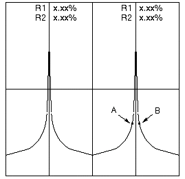
- Select Window and Two Windows from the Window menu. On the double window two peaks will display
that should be approximately the same amplitude within 50%. (See Figure 4.)
Figure 4. Typical Grafidy Prescan
- Select Done.
- Select Auto Prescan.
- If Auto Prescan fails, adjust the rotary step attenuator to 30 db (from 20 db). Occasionally, it may need to be adjusted to 10 db instead (from 20 db). Auto Prescan again until it is successful.
- Continue to Grafidy 3 Auto Mode and Manual Mode or Jump Back to Main Menu.
3 Finalization
Finalization
No finalization steps.