Control Board for XFA
Prerequisites
Procedure
- Remove L Upper Front Cover. Refer to SC Cover Removal.
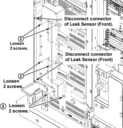
- Disconnect the two connectors of leak sensor assy.
- Remove the cabinet leak sensor assy by loosening 6 screws.
Figure 1. Remove Leak Sensor
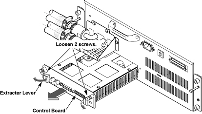
- Loosen 2 screws of control board for XFA.
- Open two extractor levers, and remove control board from XFA. note:
The control board can be removed/inserted to the socket by lifting up a little.
Figure 2. control board
- Restore control board for XFA by reverse order.
- Restore the cabinet leak sensor assy.
- Restore System Cabinet.
1 Finalization
Procedure
- Restore the Power. Refer to System Cabinet PDU Main Breaker LOTO Procedure.
- To adjust DC Offsets, refer to DC Offset Adjustment.
- Perform [TPS Reset].
- Perform DQA Tool.
- Perform Signal to Noise - Head Scan.