- id_13107538
- Version: 3.0
- Date: Aug 29, 2019 1:34:36 AM
Operator Display and Control Panels Replacement
Prerequisites
| Required persons | Preliminary requirements | Procedure | Finalization |
|---|---|---|---|
| 1 | 5 minutes | 45 minutes | 5 minutes |
| Item | Quantity | Effectivity | Part number | Manufacturer |
|---|---|---|---|---|
| Non-Magnetic Tool Kit | 1 | - |
5112581 |
- |
| Item | Quantity | Effectivity | Part number | Manufacturer |
|---|---|---|---|---|
| In-Room Display (option) | 1 | - |
See FRU Manual |
- |
| Trackball Control Panel (option) | 1 | - |
See FRU Manual |
- |
| E-Stop Panel | 1 | - |
See FRU Manual |
- |
| Standard Right Control Panel | 1 | - |
See FRU Manual |
- |
| Standard Left Control Panel | 1 | - |
See FRU Manual |
- |
|
This document provides the procedures for replacing operator control/display hardware in the front magnet enclosure. This document covers both the in-room display (IRD) version and the version without the IRD.
Replacing In-Room Display
Procedure
- Perform LOTO on the PGR PDU/gradient subsystem. See the MR Service Safety Manual, PN 5452735.
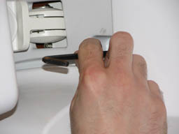
- note:Remove the laser light cover. It is held in place by two screws and a popper.
The PDU must be powered down completely to prevent damage to system electronics.
Figure 1. In-Room Display (IRD)
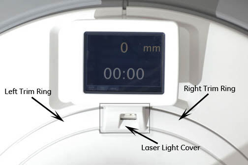
Figure 2. Removing Laser Light Cover
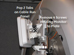
- Remove top panel on back of the IRD by popping tabs with a small
flat head screwdriver.
Figure 3. Removing IRD
 warning
- Disconnect the three cables attached to the IRD (ground cable, fiber optic cable, and power cable).
- Remove four Allen head screws connecting the bracket plate to the back of the IRD. Lift the monitor up and off the bracket carefully, because eddy currents may pull against it.
- Mount the new IRD, reconnect the appropriate cables, and replace the covers.
 |
Replacing Trackball Control Panels and E-Stop Button
Procedure
- Perform LOTO on the PGR PDU/gradient subsystem. See the MR Service Safety Manual, PN 5452735.
- note:Remove the front panels. See Front Cover Removal and Installation.
The PDU must be powered down completely to prevent damage to system electronics.
Figure 4. Removing Front Cover
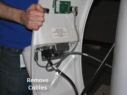
- Disconnect the two cables that connect the control panels to
the magnet enclosure.note:
If cable connectors are not labeled with a J number, mark the applicable J number on each cable connector before removal.
Figure 5. Removing Control Panel Cables
- warning
- Remove the trackball control panel by removing five screws and
detaching the emergency stop (e-stop) button cable.
Figure 6. Removing Trackball Control Panel
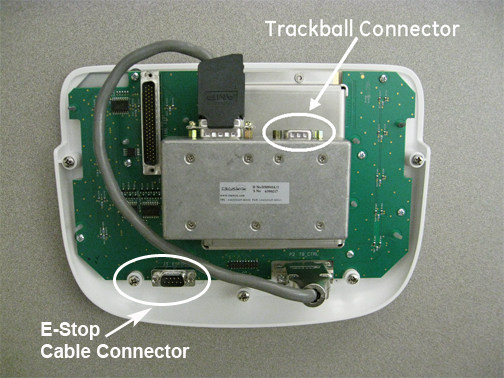
 note:
note:If you are only replacing the e-stop button board, disconnect the e-stop cable and remove two screws. Install the new button.
Figure 7. Trackball Connector
- notice
- To install the new trackball control panel, follow Step 2 through Step 4 in reverse
order.
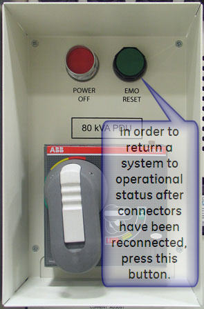
Figure 8. EMO Reset on PDU
|
 |
Replacing Standard Control Panels
Procedure
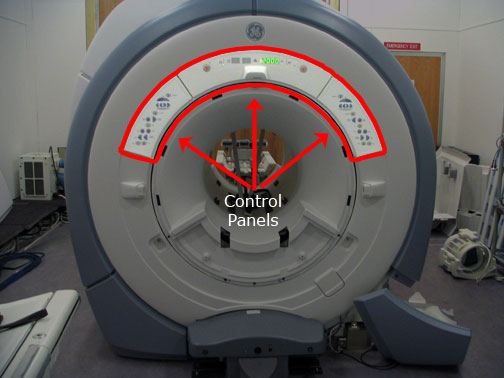
- The three control panels can be removed independently.
Figure 9. Location of Control Panels
- Perform LOTO on the PGR PDU/gradient subsystem. See the MR Service Safety Manual, PN 5452735.
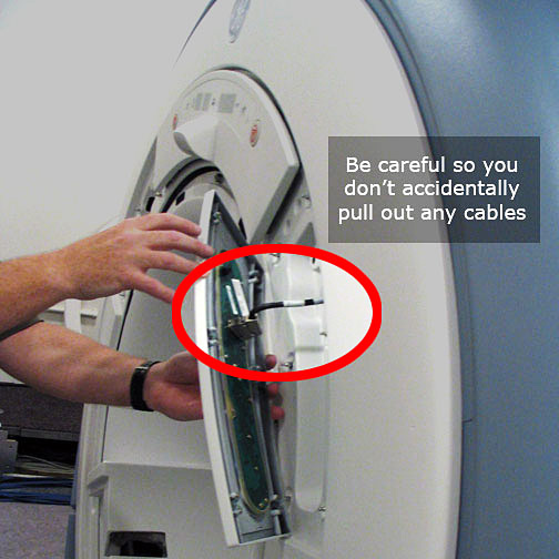
- note:These panels are secured with poppers, but have hidden cables attached to each of them. Pull the control panels away from the cover, being careful not to pull the cables out.
The PDU must be powered down completely to prevent damage to system electronics.
Figure 10. Removing Control Panels
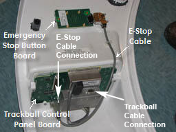
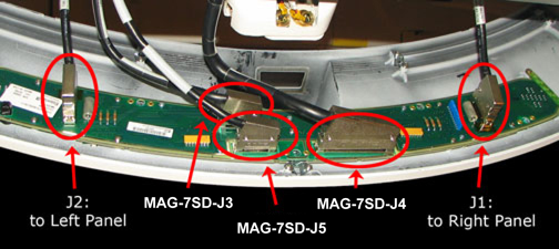
- After the panels are free from the enclosure, detach all the
cables from each control panel.
Figure 11. Connection Locations
- To replace the control panels, reverse the above steps.
Figure 12. EMO Reset on PDU
Finalization
Procedure
- Remove LOTO from the PGR/PDU and power on the PDU. See the MR Service Safety Manual, PN 5452735.
- Whenever the IRD or trackball control panels are disconnected and then reconnected, a TPS reset must be completed. (This is not necessary if the host computer is rebooted.)
- Check the functionality of the item replaced. Run the associated
diagnostic, if necessary.
-
For the IRD: From the Common Service Desktop, select Diagnostics > Hardware Location > Magnet Room > In Room Display.
-
For the control panel: From the Common Service Desktop, select Diagnostics > Hardware Location > Magnet Room > SRI Functional Tests.
-