- id_13107057
- Version: 3.0
- Date: Aug 29, 2019 1:53:36 AM
1.5T 12-Channel Body Array Coil Setup for MCQA Test
Prerequisites
| Required persons | Preliminary requirements | Procedure | Finalization |
|---|---|---|---|
| 1: Unified Phantom or 2: Legacy Phantom (HDx/HDxt only) | Not Applicable | 30 minutes | Not Applicable |
| Item | Quantity | Effectivity | Part number | Manufacturer |
|---|---|---|---|---|
| Legacy Phantom Positioner Kit (Spherical Positioner, Cylindrical Positioner) | 1 | Legacy Phantom Set |
2424388, 2424357, 2424358 |
- |
| MR450 System Phantoms | 1 | Legacy Phantom Set |
2135652, 2274476, 2135650 |
- |
| TL Unified Phantom | 2 | Unified Phantom Set |
5343347 |
- |
| Condition | Reference | Effectivity |
|---|---|---|
|
The following coil configuration names must be installed to run this tool: GE_HDx BodyUpper and GE_HDx BodyLower. |
- | - |
|
The following coil configuration names must be installed to run this tool: GE_HDx BodyUpper and GE_HDx BodyLower. |
- | - |
|
The following coil configuration names must be installed to run this tool: GE_HDx BodyUpper2 and GE_HDx BodyLower2. |
- | - |
Follow this process to prepare for the automated SNR test using the 12-Channel Single or Dual Connector Body Array Coil by GE/USAI.
Coils do not ship with phantoms. Phantoms come in a unified phantom set with the MR system.
MCQA Setup for System Phantoms (MR450)
Procedure
- note:Place the posterior section of the coil on the cradle, so the end with the system cable is approximately 24 in. from the face of the magnet (Figure 1).
In Figure 2 through Figure 11, the Green arrow indicates the direction of the bore.
If installing the coil for the first time in the system, refer to Auto Coil Install.
Figure 1. Posterior Section in Cradle
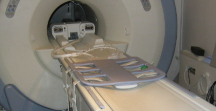 note:
note:Figure 1 is for the HDx system, but the same setup is applicable to the MR450 system. The P-Connector (MR450 system) cable will go to receptacle P.
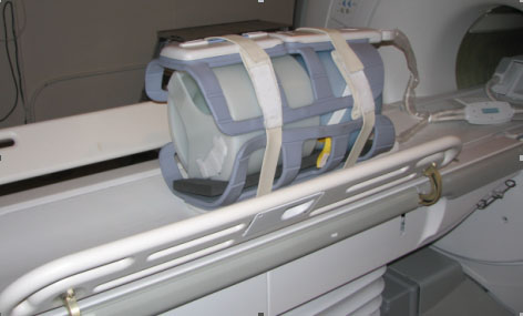
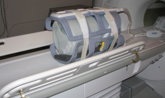
- Raise the table wings when positioning the phantoms for this
setup as shown in Figure 2. Failure to raise the table wings may cause
the phantoms to roll off the table.
Figure 2. Table Wings Raised with Coil Connected to System
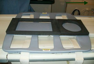
- Place the phantom positioner onto the coil as shown in Figure 3.
Figure 3. Phantom Positioner Set on Coil
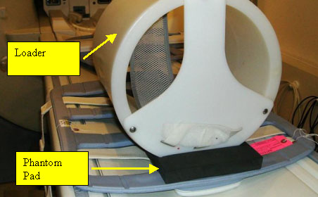
- Position the cylindrical loader (P/N 2135652) onto the appropriate
positioner as shown in Figure 5.
- Ensure the arrow on the loader is pointing in the opposite direction
from the bore (Figure 4).
Figure 4. Blue Spherical Phantom into Loader
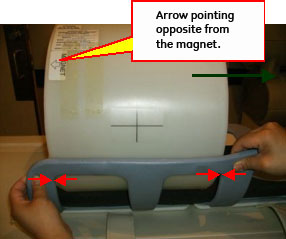
- Center the loader on the coil and on the cradle, then align phantom edges with the inside corners of the coil’s frame as shown in Figure 4.
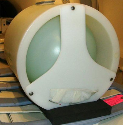
Figure 5. Cylindrical Loader Centered into Coil
- Ensure the arrow on the loader is pointing in the opposite direction
from the bore (Figure 4).
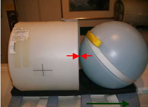
- Insert the spherical phantom (P/N 2135650) into the cylindrical
loader (Figure 6).
Figure 6. Cylindrical Loader with Blue Spherical Phantom into Coil
- Position the center portion of LVShim phantom (P/N 2274476)
onto the positioner, and ensure it touches the wall of the cylindrical
loader (Figure 7).
Figure 7. Phantom Setup
- Position the anterior of the body array coil onto the phantoms,
and line up the inside corners of the frame (Figure 8).
Figure 8. Position Anterior of Coil onto Phantom
- Place foam pads on the right and left side of the phantom/phantom holder to ensure the phantom will not roll off the table during setup.
- Secure the coil in place using the Velcro straps. Place one
strap on cylindrical loader, and fold the other strap (Figure 9).
Figure 9. Velcro Strap and Folded Strap at Cylindrical Loader
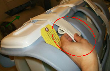 note:
note:Ensure that the Velcro strap is folded as shown in Figure 9. If the strap is not folded, damage to the coil is possible when the cradle is inserted/removed from the bore.
- If the anterior connector is unplugged, plug connector into
anterior of the coil (Figure 10).
Figure 10. Connect Anterior Connector into Anterior
- Connect the P-Connector system cable into the P port (Figure 11).
Figure 11. Coil Connected to System
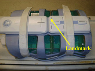
- Landmark at the center landmark of the anterior part of coil as shown in #id_SL2724814-1087042/SL2724522-1087042.
- After coil and phantom are properly positioned, perform Multi-Coil Quality Assurance (MCQA) Tool if available, otherwise perform the Surface Coils SNR Test.
TL Unified Phantom Setup
Procedure
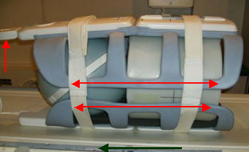
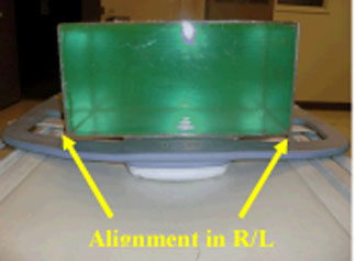
- Place the posterior section of the coil on the table. Place
the TL unified phantoms over the posterior section as shown in Figure 12 such that the
phantoms are well centered on both S/I direction as shown in Figure 13 and R/L direction
as shown with arrows in Figure 14.
Figure 12. TL Unified Phantoms Over Posterior Section
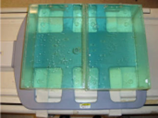
Figure 13. TL Unified Phantoms Centered on Posterior S/I Direction
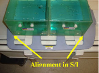
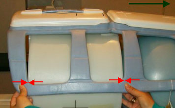
Figure 14. TL Unified Phantoms Centered on Posterior R/L Direction
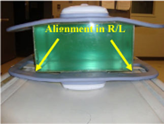
- Place the anterior section on the phantoms such that the coil
is well centered in both S/I and R/L directions with respect to the
phantom set as shown in the Figure 15 and Figure 16.
Figure 15. TL Unified Phantoms Centered on Anterior S/I Direction
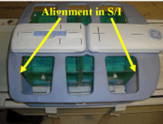
Figure 16. TL Unified Phantoms Centered on Anterior R/L Direction
- Fasten the Velcro straps so that the coil firmly snugs the phantoms.
- Connect the coil to Port P of the system LPCA. Landmark the
coil at the center cross mark as shown in the following illustration
and advance to scan.
Figure 17. Landmarking Coil
- After coil and phantom are properly positioned, perform Multi-Coil Quality Assurance (MCQA) Tool.
Finalization
Finalization
No finalization steps.