- id_13106341
- Version: 2.1
- Date: Nov 20, 2019 10:45:21 AM
Dell T5810 Troubleshooting
Overview
The following information may help resolve problems with the Dell T5810 PC.
The FRUs associated with the Dell T5810 are: the two SSDs, DVD-RW drive, CMOS battery and the PC. See Dell T5810 Lower Level FRU Replacement.
 |
|

 |
|
Dell vendor diagnostics
Diagnostic LEDs
| Power LED state | System state | Notes |
|---|---|---|
| Off | S5/S4 | Normal - The system is Off/Hibernate |
| Blinking White | S3 | Normal - The system is in Standby/Suspend |
| Blinking Amber | N/A | Abnormal - If the PSU does not start, run the PSU BIST. Replace the PSU. |
| Steady White | S0 | Normal - The system is on and operates correctly |
| Steady Amber | N/A | Abnormal - The system will not start. Check the motherboard components, or replace the motherboard. |
| Blink pattern | System state | Notes |
| 2,1 | A possible system motherboard failure has occurred. | Replace the motherboard. |
| 2,2 | A possible PSU or cabling issue has occurred. | Run the PSU BIST. Check the PSU cabling to the motherboard to make sure that all cables are installed correctly. |
| 2,3 | A possible motherboard, memory, or CPU failure has occurred. | If two or more memory modules are installed, remove the modules, and then reinstall one module and restart the computer. If the computer starts normally, continue to install additional memory modules (one at a time) until you have identified a faulty module or reinstalled all modules without error. |
| 2,4 | A possible coin cell failure has occurred. |
Replace the CMOS battery. |
| 2,5 | The system is in Recovery Mode. | BIOS checksum failure was detected and the system is now in recovery mode. |
| 2,6 | A possible processor failure has occurred. | Re-seat the processor. |
| 2,7 | The system finds the memory modules, but a memory power failure has occurred. | If two or more memory modules are installed, remove the modules, and then reinstall one module and restart the computer. If the computer starts normally, continue to install additional memory modules (one at a time) until you have identified a faulty module or reinstalled all modules without error. |
| 3,1 | PCI device configuration activity is in progress or PCI device failure was detected. | Remove all peripheral cards from the PCI and PCI-E slots and reboot the computer. If the computer boots, add the peripheral cards back one by one until you find the bad one. |
| 3,2 | A possible HDD or USB failure has occurred. |
Remove all external USB connections to the PC. Re-seat all power and data cables to HDDs. Reinstall all USB devices and check all cable connections. |
| 3,3 | No memory modules are installed. |
If two or more memory modules are installed, remove the modules, then reinstall one module and restart the computer. If the computer starts normally, continue to install additional memory modules (one at a time) until you have identified all modules without error. If available, install working memory of the same type into your computer. |
| 3,4 | Power connector not installed properly. | Re-seat the 2x2 power connector from the power supply unit. |
| 3,5 | Memory modules are detected, but a memory configuration or compatibility error has occurred. | Make sure that no special requirements for memory module or connector placement exist. Make sure that the memory you are using is supported by your computer. |
| 3,6 | A possible system board resource and/or hardware failure has occurred. | Clear CMOS (re-seat the coin-cell battery). |
| 3,7 | Some other failure has occurred. |
|
Disk drive configuration
Figure 1. Hard drives with wiring harness connections
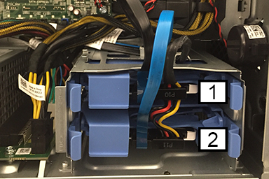
| Item | Power | Data | Contents |
| 1 | HDD1 - DATA | SSD | Image data |
| 2 | HDD0 - Boot Drive | SSD | Application software |
Video output troubleshooting
Figure 2. Nvidia Quadro K620 graphic cards
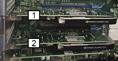
| Item | Description |
| 1 | Slot PCI2, system monitor |
| 2 | Slot PCI4, IRD monitor |
Error messages
There are three types of BIOS error messages that are displayed depending on the severity of the issue:
- Errors That Halt Your Computer Completely: These error messages will halt the computer requiring you to cycle the system's power. The following table lists the error messages.
- Errors That Do Not Halt Your Computer: These error messages will not halt your computer, but will display a warning message, pause for a few seconds, and then continue to boot. The following table lists the error messages.
- Errors That Soft Halt Your Computer: These error messages will cause a soft halt of your computer and you will be prompted to press F1 to continue or F2 to enter the system setup.
| Type | Error |
|---|---|
| Errors That Halt Your Computer Completely |
|
| Errors That Do Not Halt Your Computer | Alert! Cover was previously removed. |
| Errors That Soft Halt Your Computer |
|