Probe signal-to-noise ratio (SNR) performance test
Procedure
Note: The Probe-S tuning procedure requires the site to have purchased catalog M3333WH. The following procedure does not run if the Probe-P option was purchased.
If there is an exam running, end the current exam (unless the exam was started with the “geservice” patient ID).
Figure 1. Install Curved Adapter Panel for Flat Table
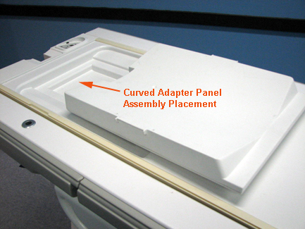
Figure 2. Install Service Filler Panels for Curved Table
Insert the curved adapter panel into the table.
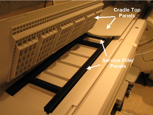
Install a service filler panel under each of the two cradle top panels.
Figure 3. Install Service Filler Panels
Position the MRS phantom in the single channel head coil. Do NOT use the head loader with the MRS phantom. Use foam support pads for quick alignment to center the phantom in the head coil. Phantom centering (up/down/left/right/in/out) within 5 mm of the isocenter in all directions is important. Landmark on the center of the phantom.
Run a 3-plane localizer to make sure the MRS phantom is properly centered. If necessary, perform an additional 3-plane localizer. After the phantom is centered, make sure the phantom remains stationary for at least 5 minutes before the start of any probe calibration scan. (This is to allow the fluid in the phantom to reach equilibrium and to minimize the effects of long-term eddy currents.)