
- 00000018WIA3088B950GYZ
- id_20260552.0
- Feb 22, 2021 1:44:41 AM
Checking the hose and valve connection
Prerequisites
| Personnel requirements | |||
|---|---|---|---|
| Required persons | Preliminary requirements | Procedure | Finalization |
| Tools and test equipment | |||
|---|---|---|---|
| Item | Quantity | Part number | Manufacturer |
| Consumables | |||
|---|---|---|---|
| Item | Quantity | Part number | Manufacturer |
| Replacement parts | |||
|---|---|---|---|
| Item | Quantity | Part number | Manufacturer |
| Required conditions |
|---|
| Safety |
|---|
|
Before working in any GE Healthcare MR suite or performing any GE Healthcare service procedure, you must:
If you have any safety concerns at any time, do not begin work or immediately stop work and move to a safe location. Immediately contact your supervisor or site safety officer for instructions on how to proceed. |
About this task
Procedure
- Inspect the orientation of the check valves in the blue, black, green, and red hoses.
Orientation should be per the schematic in Figure 1. The check valves in the supply hoses to the PGR cabinet (green) and the gradient coil (blue) should have the flow arrow pointing away from the HEC. The check valves in the return hoses from the PGR cabinet (red) and the gradient coil (black) should have the flow arrow pointing towards the HEC.
If any valve is reversed, do not proceed with the procedure until the check valve is properly installed.
Figure 1. HEC Coolant Schematic 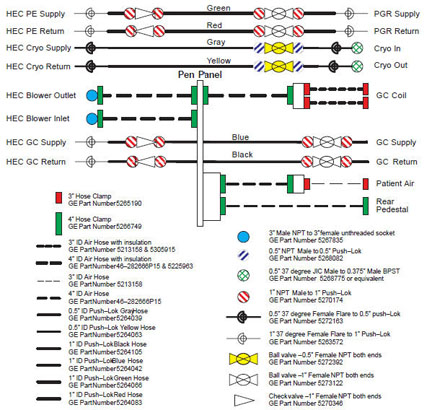
To view a high-resolution image of this schematic, , available from the online documentation library.
- If there is an issue with any of the connections, retighten or reapply new Teflon tape as needed before adding any coolant to the system.
- To apply new Teflon tape, start one thread in from the end of the male NPT fitting. Doing so will prevent tape from entering the fluid passage.
Figure 2. Applying New Teflon Tape 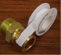
- Because Teflon tape is not adhesive-backed, hold the end of the tape with a finger until one full wrap is completed. Wind the tape in a clockwise direction (as viewed from the end of the fitting). This ensures that the installation of the mating components results in wrapping the tape in the same direction and not unraveling or unwinding it.
Figure 3. Correct Application of Teflon Tape 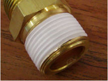
- After the first wrap, continue wrapping in a clockwise direction with moderate tension applied to the tape roll. Overlap the prior layer by a half width of the tape as shown in Figure 4. This ensures that two layers of tape cover all threads of the fitting.
Figure 4. Teflon Tape Overlap 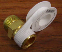
- To apply new Teflon tape, start one thread in from the end of the male NPT fitting. Doing so will prevent tape from entering the fluid passage.