- 00000018WIA304A9D30GYZ
- id_20128505.0
- Dec 23, 2020 10:23:03 AM
Dummy load resistance check and setup
About this task
| DANGER | |
|---|---|
Procedure
- Use a DVM to measure the resistance of input to the dummy load.
- Measure directly on the dummy load input connector – center pin to GND.
Figure 1. Measure dummy load input resistance 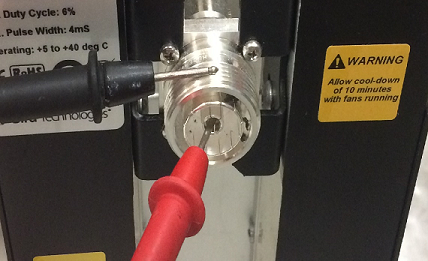
- Measure directly on the dummy load input connector – center pin to GND.
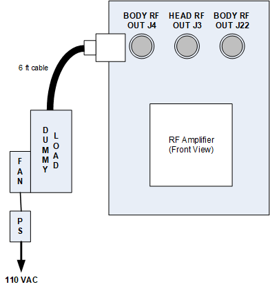
- Do the dummy load setup. Plug the fan for the dummy load into a service outlet. Never use this dummy load without its fan running.
Notice Figure 2. Connect dummy load