- Optima MR450w BASE 1.5T System Service Methods
- 5690012-2EN Revision 3
- 00000018WIA30A40130GYZ
- id_123734301.4
- Jul 5, 2019 10:03:32 PM
XGD Cronus Chassis Replacements
Prerequisites
| Required persons | Preliminary requirements | Procedure | Finalization |
|---|---|---|---|
| 1 | Not Applicable | 45-60 minutes | Not Applicable |
| Item | Quantity | Effectivity | Part number | Manufacturer |
|---|---|---|---|---|
| Small Phillips Screwdriver | 1 | - | - | - |
| Slotted Screwdriver | 1 | - | - | - |
| Item | Quantity | Effectivity | Part number | Manufacturer |
|---|---|---|---|---|
| XGD Gradient Master Control (GMC) Board | 1 | - |
5250128 | - |
| XGA Control Board | 1 | - |
5250122 | - |
| XPS Control Board | 1 | - |
5250122-2 | - |
| XGD Cronus Power Supply | 1 | - |
5159513 | - |
| XGD Cronus Fan Assembly | 1 | - |
5183573 | - |
| XGD Cronus Chassis | 1 | - |
2384411 | - |
| Condition | Reference | Effectivity |
|---|---|---|
|
Use an ESD wristband when replacing all components. When removing paired fiber optics, grip by the black band at the connector base to retract. | - | - |
About this task
Overview
This document includes replacement procedures for the following:
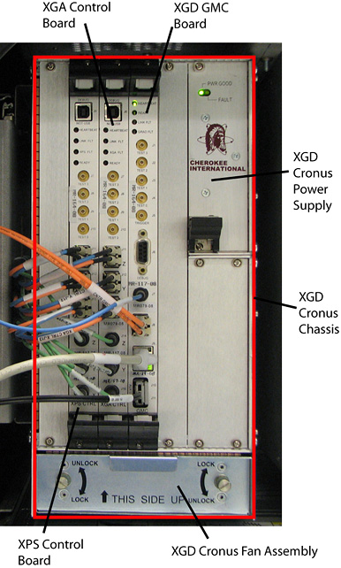
XGD Gradient Master Control (GMC) Board
Removing XGD GMC
Procedure
- Perform LOTO on the PGR cabinet. See the MR Service Safety Manual, PN 5452735.
- Remove cables J7, J8, J9, and J10/J11.
- Loosen the top and bottom screws securing the XGD GMC.
- Using your thumbs, push in and then gently pull the extractor tab located on the top and bottom of the XGD GMC. The lever action of the ejectors disengages the XGD GMC from the XGD Cronus chassis.
- Slide the XGD GMC all the way out of the XGD Cronus chassis.
Installing XGD GMC
Procedure
- Use the ejectors to insert the new XGD GMC into the XGD Cronus chassis.
- Tighten the top and bottom screws to secure the XGD GMC.
- Attach cables J7, J8, J9, and J10/J11.
XGA Controller Board
Removing XGA Controller Board
Procedure
- Perform LOTO on the PGR cabinet. See the MR Service Safety Manual, PN 5452735.
- Remove cables J11, J12, J13, J14, J15, and J16.
- Loosen the top and bottom screws securing the XGA controller board.
- Using your thumbs, push in and then gently pull the extractor tab located on the top and bottom of the XGA controller board. The lever action of the ejectors disengages the XGA controller board from the XGD Cronus chassis.
- Slide the XGA controller board all the way out of the XGD Cronus chassis.
Installing XGA Controller Board
Procedure
- Use the ejectors to insert the new XGA controller board into the XGD Cronus chassis.
- Tighten the top and bottom screws to secure the XGA controller board.
- Attach cables J11, J12, J13, J14, J15, and J16.
XPS Controller Board
Removing XPS Controller Board
Procedure
- Perform LOTO on the PGR cabinet. See the MR Service Safety Manual, PN 5452735.
- Remove cables J11, J12, J13, J14, J15, and J16.
- Loosen the top and bottom screws securing the XPS controller board.
- Using your thumbs, push in and then gently pull the extractor tab located on the top and bottom of the XPS controller board. The lever action of the ejectors disengages the XPS controller board from the XGD Cronus chassis.
- Slide the XPS controller board all the way out of the XGD Cronus chassis.
Installing XPS Controller Board
Procedure
- Use the ejectors to insert the new XPS controller board into the XGD Cronus chassis.
- Tighten the top and bottom screws to secure the XPS controller board.
- Attach cables J11, J12, J13, J14, J15, and J16.
XGD Cronus Power Supply
Removing XGD Cronus Power Supply
Procedure
- Perform LOTO on the PGR cabinet. See the MR Service Safety Manual, PN 5452735.
- Loosen the top and bottom screws securing the XGD Cronus power supply.
- Using your thumbs, push in and then gently pull the extractor tab located on the bottom of the XGD Cronus power supply. The lever action of the ejectors disengages the XGD Cronus power supply from the XGD Cronus chassis.
- Slide the XGD Cronus power supply all the way out of the XGD Cronus chassis.
Installing XGD Cronus Power Supply
Procedure
- Insert the new XGD Cronus power supply fully into the XGD Cronus chassis.
- Tighten the top and bottom screws to secure the XGD Cronus power supply.
XGD Cronus Fan Assembly
Removing XGD Cronus Fan Assembly
Procedure
- Perform LOTO on the PGR cabinet. See the MR Service Safety Manual, PN 5452735.
- Rotate both thumb screws to the UNLOCK position.
- Pull out the XGD Cronus fan assembly from the XGD Cronus chassis using the handle provided (top of fan).
Installing XGD Cronus Fan Assembly
Procedure
- Insert the new XGD Cronus fan assembly fully into the XGD Cronus chassis.
- Rotate both thumb screws to the LOCK position.
XGD Cronus Chassis
Removing XGD Cronus Chassis
Procedure
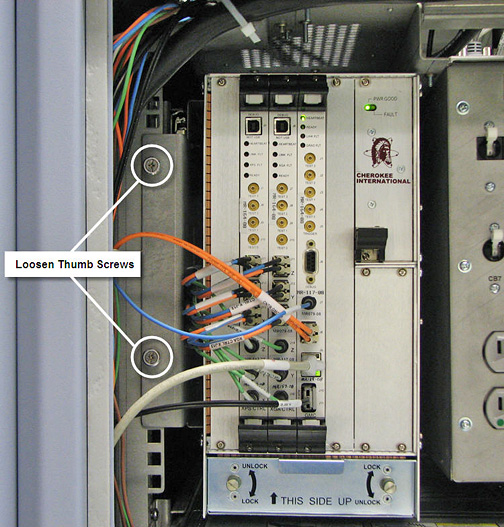
- Loosen the two thumb screws located to the left the chassis.
Figure 2. XGD Cronus Chassis Thumb Screws