
- Optima MR450w BASE 1.5T System Service Methods
- 5690012-2EN Revision 3
- 00000018WIA30FF7030GYZ
- id_123743411.2
- Jul 5, 2019 10:24:08 PM
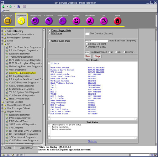
I/O Data
Diagnostic Link
Diagnostics >> System Function >> RF >> UPM Diagnostics
Diagnostics >> Hardware Location >> PGR Cabinet >> CAM >> UPM Diagnostics
Purpose
The UPM Diagnostic reads the power supply information from the UPM board.
Components Tested
-
Chassis Power Supply
-
Isolated 5 Volts
-
FPGA Initialization
-
Flash Power
-
RF NB Board and Cable
-
RF MNS Board and Cable
-
Unblank Cable
-
RF NB Negative 12 Volt
-
RF MNS Negative 12 Volt
Requirements
No special requirements.
Test Sequence
-
Select the I/O Data test from the UPM Diagnostics screen.
-
Modify Test Parameters as necessary.
-
Click the Run button.
Expected Results
A blue color indicates a normal result. A red color indicates an error.