
- Optima MR450w BASE 1.5T System Service Methods
- 5690012-2EN Revision 3
- 00000018WIA30578230GYZ
- id_156668241.8
- Jul 3, 2020 11:29:39 PM
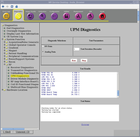
Doing the Universal Power Monitor (UPM) analog data diagnostic
The Universal Power Monitor (UPM) diagnostic reads the power supply information from the UPM board.
Disclaimer
Depending on your service agreement, not all service tools, diagnostics, and utilities referenced in this document may be accessible. Contact your sales person for information on available service license packages.
Diagnostic description
Diagnostic path
Purpose
The UPM diagnostic reads the power supply information from the UPM board.
Components tested
- UPB Negative 12 Volt
- UPB Positive 12 Volt
- RFNB Positive 12 Volt
- RFBB Positive 12 Volt
- UPB Positive 5 Volt
- RFNP Positive 5 Volt
- RFBB Positive 5 Volt
- UPB Positive 3.3 Volt
- RFNP Positive 3.3 Volt
- RFBB Positive 3.3 Volt
- UPB Positive 1.5 Volt
- UPB Positive 1.65 Volt
- RFNP VREF
- RFBB VREF
- RFNP Board Temperature
- RFBB Board Temperature
Requirements
- No special requirements.
Test sequence
- On the UPM Diagnostics screen, select Analog Data.
- Modify Test Parameters as necessary.
- Click Run.
The Analog Data test reads the power supply information from the UPM board every 5 seconds for the specified test duration (max 300 seconds). No error messages will be logged for failing power supplies since the applications code will be logging these errors automatically.
Results
A blue color indicates a normal result.