- Topic ID: id_17423027
- Version: 4.0
- Date: Jan 20, 2020 8:32:45 PM
Backplane Replacement - Merc40
Prerequisites
Overview
This procedure defines the necessary steps to Remove and Install the Backplane.
1 Preparation
Procedure
- Move table to home position, fully out and down.
- Remove right side gantry cover.
Refer to Parts Replacement → Gantry → Enclosure → (Cover Removal Procedure).
- Stop the rotor of X-ray tube in case of Liquid Bearing Tube before HVDC off. Refer to Liquid Bearing Tube Rotor stop procedure for details.
- Turn OFF the Axial Drive and HVDC switches on the gantry’s Service Switch Panel.
- Position the detector at 12 o'clock and lock gantry rotation.
- Turn OFF the 120 VAC switch on the gantry’s Service Switch Panel.
- Remove the gantry left side cover, top covers and front cover.
2 Removal Procedure
Procedure
- Cover the Tube Collimator port to protect it against dropped tools or screws. (Cloth or any other available item)
- Remove the Air Plenum as shown in Detector Air Plenum Removal/Installation.
- Remove the CDCB as shown in CDCB Replacement.
- Remove the power board as shown in Power Board Replacement.
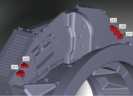
- Disconnect cable connectors (J30, J31, J32, J33 and J51) from
the back side of the DAS assembly.
Figure 1. Cable Connectors of Backplane
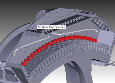
- Disconnect 27 module connectors from the backplane.
Figure 2. Module Connectors
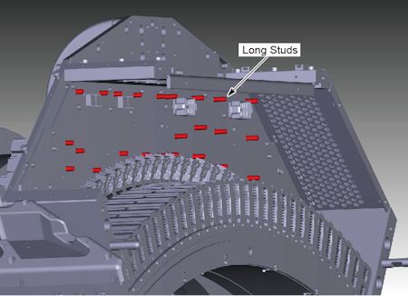
- Remove long studs of CDCB and power board from the backplane.
Figure 3. Long Studs of CDCB and Power Board
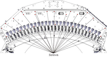
- Remove screws holding the backplane to the base frame of DAS/Detector.
Figure 4. Screws of Backplane
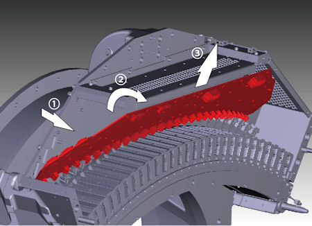
- Hold the backplane, and tilt it slightly forward, then remove
it upward.
Figure 5. Backplane Removal
3 Installation Procedure
Procedure
- Attach the new backplane to the base frame of DAS/Detector.
- Tighten the screws to fix the backplane to the base frame of DAS/Detector.
- Install the long studs of CDCB and power board.
- Connect the 27 module connectors.
- Connect the cable connectors (J30, J31, J32, J33 and J51) to the back side of the DAS assembly.
- Install the power board as shown in Power Board Replacement.
- Install the CDCB as shown in CDCB Replacement.
- Install the Air Plenum as shown in Detector Air Plenum Removal/Installation.
- Remove the cloth or any other item from the tube collimator port.
4 Gantry Reassembly
Procedure
- Make sure the Axial Drive, HVDC and 120 VAC switches on the gantry’s Service Switch Panel are OFF.
- Release the gantry rotational lock and install gantry covers,
all except the right side cover.
Refer to Replacement → Gantry → Enclosure → (Cover Removal Procedures).
- Turn on the 120 VAC, HVDC and Axial drive service switches.
- Install gantry right side cover.
5 Finalization
Procedure
- Perform a [Quality Assurance Test] from the [Functional Checks] menu of the service manual to ensure system operation.
- Perform a [Save State] to save new calibration data.