- Topic ID: id_17423226
- Version: 5.0
- Date: Jan 20, 2022 8:46:49 PM
CDCB Replacement - Merc40
Prerequisites
Overview
This procedure defines the necessary steps to Remove and Install the CDCB.
1 Preparation
Procedure
- Move table to home position, fully out and down.
- Remove right side gantry cover.
Refer to Parts Replacement → Gantry → Enclosure → (Cover Removal Procedure).
- Stop the rotor of X-ray tube in case of Liquid Bearing Tube before HVDC off. Refer to Liquid Bearing Tube Rotor stop procedure for details.
- Turn OFF the Axial Drive and HVDC switches on the gantry’s Service Switch Panel.
- Position the detector at 12 o'clock and lock gantry rotation.
- Turn OFF the 120 VAC switch on the gantry’s Service Switch Panel.
- Remove the gantry left side cover, top covers and front cover.
2 Removal Procedure
Procedure
- Cover the Tube Collimator port to protect it against dropped tools or screws. (Cloth or any other available item)
- Remove the Air Plenum as shown in Detector Air Plenum Removal/Installation.
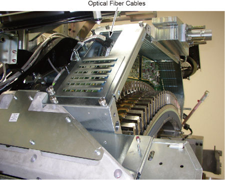
- Disconnect 2 optical fiber cables from CDCB.
Figure 1. Optical Fiber Cables
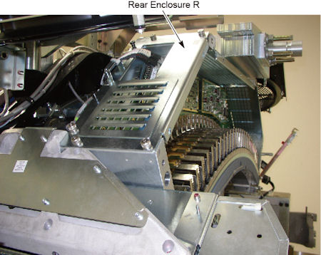
- Remove 6 screws holding the rear enclosure R to the DAS assembly,
and remove the rear enclosure R.
Figure 2. Rear Enclosure R
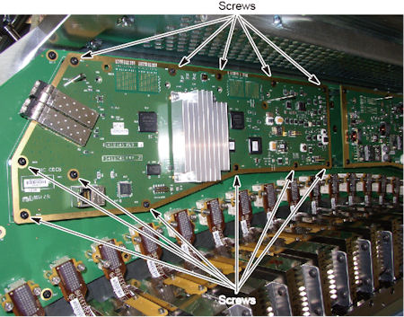
- Remove 12 screws holding the CDCB to the backplane of DAS.
Figure 3. Screws of CDCB
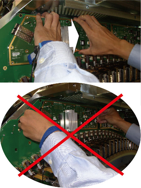
- notice
- Hold the CDCB as shown in illustration below, and carefully
and slowly wiggle or rock the CDCB, then disconnect the 2 connectors
on CDCB from the backplane at a time.
Figure 4. CDCB Disconnection
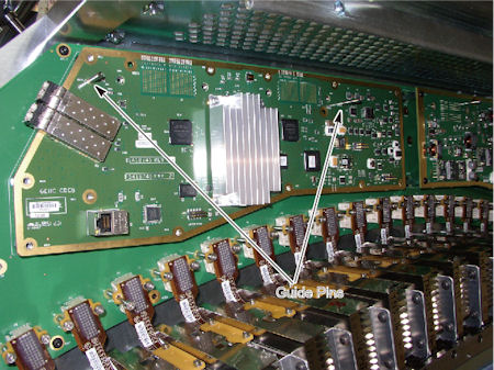
- Pull out the CDCB from the guide pins on the backplane.
Figure 5. Guide Pins
 |
3 Installation Procedure
Procedure
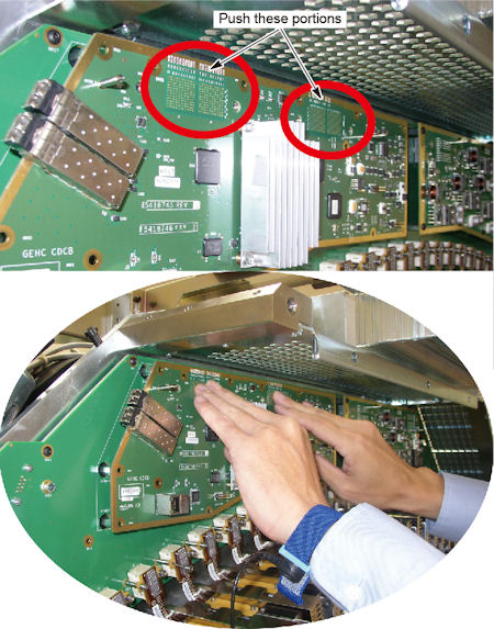
- Install the new CDCB along the guide pins.
- Push the backside of connectors on CDCB forward slightly, and
connect them to the backplane.
Figure 6. CDCB Connection
- Tighten the 11 screws to fix the CDCB to the backplane.
- Install rear enclosure R, and tighten the 6 screws.
- Connect the 2 optical fiber cables to CDCB.
- Install the Air Plenum as shown in Detector Air Plenum Removal/Installation.
- Remove the cloth or any other item from the tube collimator port.
4 Gantry Reassembly
Procedure
- Make sure the Axial Drive, HVDC and 120 VAC switches on the gantry’s Service Switch Panel are OFF.
- Release the gantry rotational lock and install gantry covers,
all except the right side cover.
Refer to Replacement → Gantry → Enclosure → (Cover Removal Procedures).
- Turn on the 120 VAC, HVDC and Axial drive service switches.
- Install gantry right side cover.
5 Finalization
Procedure
- Perform mA Noise Check by following the steps below.
- Launch Diagnostic Data Collection from Common Service Desktop.
- Go to Position Tube and set tube position to 0 deg.
- Select Static X-ray On as
Scan Type and set the following parameters. Apply default unless otherwise
specified.
-
Scan Time: 1.0 sec.
-
kV: 120
-
mA: 10
-
Trigger Rate: 984
-
Filter: Air
-
Slice Collimation: 64x0.625
-
Tracking Mode: Off
-
- Execute a scan.
- Dismiss Diagnostic Data Collection tool in Diagnostic tab of CSD.
- Launch Scan Analysis in Image Quality tab of CSD and select the scanned data.
- Select Aux Channel.
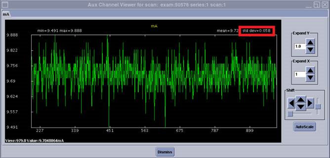
- In Aux Channel Select window, set the view number from 200 to 984 views, select mA check box and deselect Kv. Then press OK.
- Verify the standard deviation of mA is within the specs below.
If not, replace the CDCB board. Specification: Std. Dev. ≤ 0.11.
Figure 7. Scan Analysis result
- Perform a [Quality Assurance Test] from the [Functional Checks] menu of the service manual to ensure system operation.