- Topic ID: id_17423034
- Version: 4.0
- Date: Jan 20, 2020 8:33:41 PM
Power Board Replacement - Merc40
Prerequisites
Overview
This procedure defines the necessary steps to Remove and Install the Power Board.
1 Preparation
Procedure
- Move table to home position, fully out and down.
- Remove right side gantry cover.
Refer to Parts Replacement → Gantry → Enclosure → (Cover Removal Procedure).
- Stop the rotor of X-ray tube in case of Liquid Bearing Tube before HVDC off. Refer to Liquid Bearing Tube Rotor stop procedure for details.
- Turn OFF the Axial Drive and HVDC switches on the gantry’s Service Switch Panel.
- Position the detector at 12 o'clock and lock gantry rotation.
- Turn OFF the 120 VAC switch on the gantry’s Service Switch Panel.
- Remove the gantry left side cover, top covers and front cover.
2 Removal Procedure
Procedure
- Cover the Tube Collimator port to protect it against dropped tools or screws. (Cloth or any other available item)
- Remove the Air Plenum as shown in Detector Air Plenum Removal/Installation.
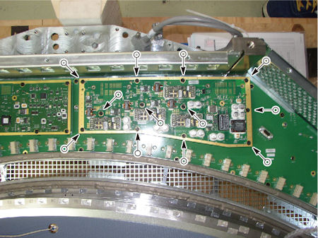
- Remove 12 screws holding the power board to the backplane of
DAS.
Figure 1. Screws of Power Board
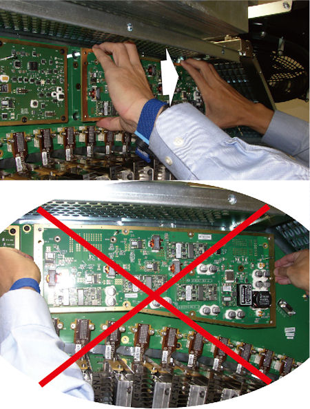
- notice
- Hold the power board as shown in illustration below, and carefully
and slowly wiggle or rock the power board, then disconnect the 2 connectors
on the power board from the backplane at a time.
Figure 2. Power Board Disconnection
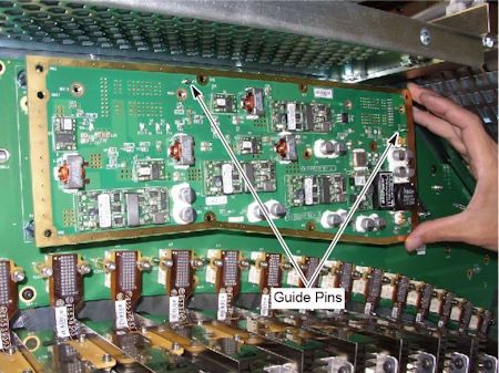
- Pull out the power board from the guide pins on the backplane.
Figure 3. Guide Pins
 |
3 Installation Procedure
Procedure
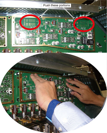
- Install the new power board along the guide pins.
- Push the backside of connectors on the power board forward slightly,
and connect them to the backplane.
Figure 4. Power Board Connection
- Tighten the 12 screws to fix the power board to the backplane.
- Install the Air Plenum as shown in Detector Air Plenum Removal/Installation.
- Remove the cloth or any other item from the tube collimator port.
4 Gantry Reassembly
Procedure
- Make sure the Axial Drive, HVDC and 120 VAC switches on the gantry’s Service Switch Panel are OFF.
- Release the gantry rotational lock and install gantry covers,
all except the right side cover.
Refer to Replacement → Gantry → Enclosure → (Cover Removal Procedures).
- Turn on the 120 VAC, HVDC and Axial drive service switches.
- Install gantry right side cover.
5 Finalization
Procedure
- Perform a [Quality Assurance Test] from the [Functional Checks] menu of the service manual to ensure system operation.