- Topic ID: id_23554308
- Version: 1.0
- Date: Oct 9, 2018 1:41:31 PM
HV Tank Replacement
Prerequisites
Overview
To replace the High Voltage Tank:
-
Disconnect Wires
-
Cap the HV tank receptacle hole
-
Replace tank
-
Verify system operation
1 Mono-Polar High Voltage Tank (MPHVT) Removal
Procedure
 warning
- Remove power to the gantry using proper Lockout / Tagout procedures.
- Remove gantry side, top, and front covers.
- Turn OFF all three switches (AXIAL DRIVE ENABLE, HVDC ENABLE, 120 VAC) on the Service Switch Panel.
- Rotate the gantry such that HVT assembly is in the 2 o'clock position, and that you can just barely reach the lower M12 tank mounting bolts. This position will ease removal and installation.
- Lock the gantry in position, using the rotational lock. Ensure that gantry rotation is locked by attempting to rotate the gantry by hand.
- Remove HV cable candlestick. You will need to cut the three tie-wraps on the inverter and the aux box clamps.
- Place a cover over the candlestick.
- Place a cap or paper towel in the top of the receptacle to prevent oil spillage and dirt from contaminating the receptacle.
- Remove EMC Box cover between Inverter and HV Tank.
- Disconnect wire connections. This includes:
-
HV Tank measure cable (from inverter)
-
Filament control (from aux box)
-
HV inverter/tank cable (from inverter)
-
- Connect the hoist hook to the tank lifting point. Remove all slack in the chain and apply light tension.
- Remove the four mounting screws, starting with the bottom then
the top. Throw these screws away; the new tank comes with mounting
hardware.
- Using the hoist, carefully lift the tank and swing it free from the gantry.
 |
2 Mono-Polar High Voltage Tank Installation
Procedure
- Lift new tank using gantry hoist.
- Set the tank on the two guide pins located on the tank bracket.
- Install the tank with the four (4) mounting bolts and washers.
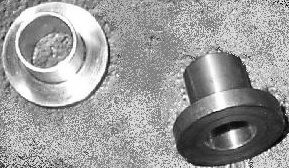
Figure 1. Adapter Bushings
Apply “preload” torque:
- Remove hoist hook from tank.
- Apply final torque to the M12 mounting bolts:
- notice
- Secure the HV cable. Reference procedure: Securing HV Cable (Pro 16).
- Reattach wiring:
-
HV Tank measure cable (from inverter)
-
Filament control (from aux box)
-
Route HV inverter/tank cables according to HV Cable Routing (Pro16) procedure
-
- Reattach EMC cover between Inverter and HV Tank.
Before reinstalling the mounting bolts, make certain to thoroughly clean all dried Loctite from the threads.
Some replacement tanks may come with four (4) adapter bushings to ensure FRU compatibility to older gantry models that use smaller diameter mount bolts. If the diameter of the existing mounting bolts on the system do not require the use of these adapters, discard them (see Figure 1).
 |
3 Finalization
Procedure
- Perform Gantry Rotation Safety Check.
- Perform Gantry Balance Procedure.
- Perform Meter Verification.
- Perform HV Tank Feedback Resistor Verification.
- Run JEDI Noise Test (Pro16, RT).
- Run Filament Calibration.
- Perform HHS Scans.
- CT Number Check
- Perform System Scanning Test.
- Perform Quality Assurance Test.
- Savestate.