- Topic ID: id_17423134
- Version: 7.0
- Date: Dec 29, 2020 1:06:05 AM
ORP Replacement (M40)
Prerequisites
Overview
This document provides the necessary steps to replace and configure the Onboard Rotation Processor Unit (ORP) for imaging.
1 ORP Assembly Removal
Procedure
- Move table to home position.
- Remove gantry right side cover.
- Stop the rotor of X-ray tube in case of Liquid Bearing Tube before HVDC off. Refer to Liquid Bearing Tube Rotor stop procedure for details.
- Turn off [HVDC ENABLE] and [AXIAL DRIVE ENABLE] switches on Service Switch panel.
- Remove power to system. See Equipment Service - Lockout-Tagout-PPE from Safety section.
- Remove scan window, gantry left side cover, gantry top covers and gantry front cover.
- Rotate gantry such that ORP assembly is in 2 o'clock position.
- Turn off [120VAC ENABLE] switch on Service Switch panel.
- Engage rotational lock. See Equipment Service - Lockout-Tagout-PPE from Safety section.
- Disconnect four front cables and one rear cable from ORP Assembly.
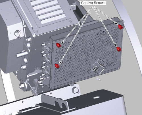
- Loosen 4 captive screws to access ORP board.
Figure 1. ORP Cover Removal
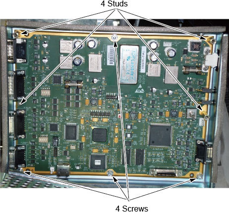
- Remove 4 screws and 4 studs, then remove ORP Assembly from gantry.
Figure 2. ORP Assembly Removal
2 ORP Assembly Installation
Procedure
- Position ORP Assembly on to gantry and fasten with three M4 mounting screws.
- Tighten each M4 mounting screw with a 3mm hex bit socket torque
wrench and 12 inch extension, to the following torque values.
- Install the bracket and connect four front cables and one rear cable to ORP Assembly.
- Route the cables by ty-wraps and metal loop, see Figure 3.
Figure 3. Cable Routing
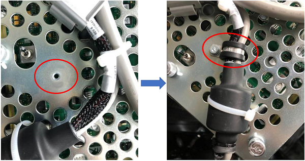
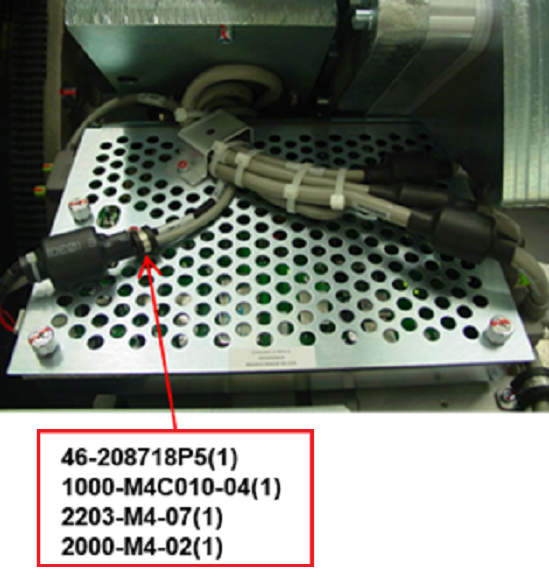 note: For cable 5328105-2, fixed in the cover with metal loop (46-208718P5), by using M4 hex screw (1000-M4C010-04), lock washer (2203-M4-07) and flat washer (2000-M4-02), apply torque of 2.3Nm. See Figure 4.
Figure 4. Fixed with metal Loop
- Disengage rotational lock. See Equipment Service - Lockout-Tagout-PPE from Safety section.
- Restore power to system. See Equipment Service - Lockout-Tagout-PPE from Safety section.
- From Console Unix Shell prompt, type touch /usr/g/fw/orpFtp and press ENTER.
- Turn on 120 VAC ENABLE, AXIAL DRIVE ENABLE, and HVDC ENABLE switches on Service Switch Panel.
- Press ESTOP RESET on Service Switch panel and wait until scan hardware is reset.
3 Setup, Checks, Alignments, and Calibrations
Procedure
- FLASH Download
- Gantry Rotation Safety Check
- Gantry Balance Procedure
- Turn off [HVDC ENABLE], [AXIAL DRIVE ENABLE] and [120 VAC ENABLE] switches on Service Switch panel.
- Install gantry front cover, gantry top covers, gantry left side cover and scan window.
- Turn on 120 VAC ENABLE, AXIAL DRIVE ENABLE, and HVDC ENABLE switches on Service Switch Panel.
- Press ESTOP RESET on Service Switch panel and wait until scan hardware is reset.
- Install gantry right side cover.
4 Finalization
Procedure
- Tube Warmup
- System Scanning Test
- Save Generator Runtime Parameters (See Save Restore Generator Runtime Parameters)
- Save System State