- Topic ID: id_16157493
- Version: 4.0
- Date: Apr 22, 2019 12:55:43 AM
Gantry Balance Procedure
Prerequisites
Overview
This procedure should be performed whenever the rotating Gantry is serviced. It is intended to 1) check or create sensitivity matrix, and 2) balance the Gantry in both static and dynamic vectors.
Procedure
- notice
- Review the information in the Safety section above.
-
The balance program will determine the number of each specific weight.
-
The physical order from front to back is critical and cannot be altered.
-
A quantity of 0 (zero) is a valid number for specific weights.
-
Each specific weight is defined by its base metal, generic name, location angle and thickness in mm.
Example:
-
Base Metal: Aluminum
-
Generic Name: SPACER
-
Location Angle: 180 DEG
-
Thickness in mm: 25.4MM
note:You may not have all plate types installed on your Gantry depending on what is needed to balance the Gantry.
-
-
- Position the Table at its lowest position.
- Remove the gantry right side cover.
- Stop the rotor of X-ray tube in case of Liquid Bearing Tube before HVDC off. Refer to Liquid Bearing Tube Rotor stop procedure for details.
- Disable Axial Drive, HVDC, and 120 VAC service switches from the service switch panel.
- Remove the Gantry left side, top, and front covers.
Refer to
- On the gantry right side, connect the front and rear cover cables containing the E-Stop circuit to the terminators on the gantry frame. Only one cable from the front and rear will connect, there is no chance to choose wrong.
 danger
- Enable the 120 VAC, HVDC and Axial Drive service switches from the service switch panel in order to run the balance test.
- Launch the Service Gantry Balance program
from the Service Desktop, Calibration tab.
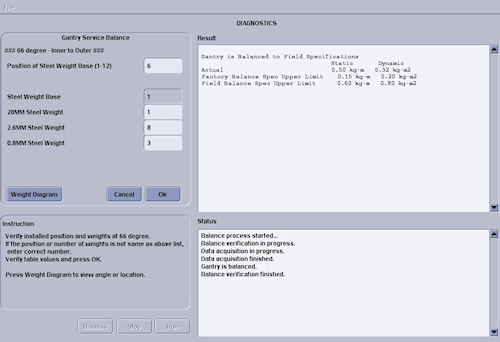
Figure 1. Sample Gantry Balance GUI
- Select Run to start the Gantry balance
procedure.note:
Follow the on-screen instructions exactly as stated. Failure to follow the steps may result in having to start the procedure from the beginning.
- The program will require extra steps if the sensitivity matrix
does not exist.
- If the sensitivity matrix does not exist, the program will ask you to enter the current weight configuration prior to performing the steps to generate a new sensitivity matrix.
- The balance program will then ask for installation of the trial weights which will require removal of the rear cover.
See Figure 6 for example of entries for 66° weight stack. The 180° weight stack appears in the same manner.
note:There is a weight diagram available via the Weight Diagram button in the GUI. See Figure 2. The diagram shown on the product supersedes any listing in this procedure.
Figure 2. Sample Weight Diagram (Cj Phase 2.5 or earlier)
Click on the PDF icon below, for a PDF version of the sample weight Diagram
Figure 3. Weight Diagram (Cj Phase 2.5 or earlier)
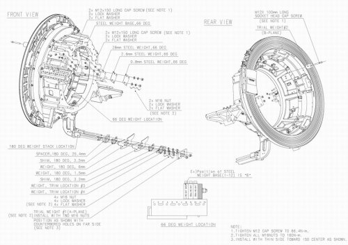
Weight_Diagram_Cj2.5Figure 4. Weight Diagram (Cj M40 or later)
Weight_Diagram_CjM40Refer to Figure 5 for trial weight placement during sensitivity matrix generation process. The trial weight on the 180 stack is placed on the end of all existing weights. Do NOT remove weights before adding the trial weight.
Figure 5. Trial Weight A and B Mounting Locations
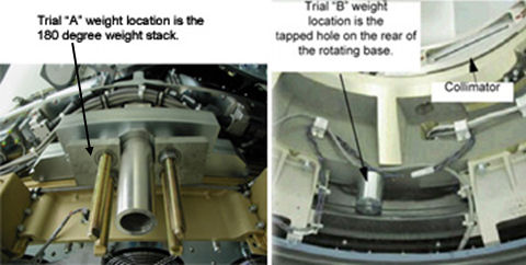
The program will ask you to place each of the two trial weights one at a time during the process.
Trial weight A at 180° position must be installed over the top of the existing weight stack and nuts such that existing nuts are in recessed holes of trial weight. Install trial weight as shown in the Weight Diagram on the system. This is the configuration and weight components expected by the program.
Figure 6. Request for Existing Weight Configuration
 note:
note:The order of the balance weights as installed on the Gantry is very important. An entry of zero is valid if the particular weight type is not currently installed.
The program will prompt for the number of specific weights in 66- and 180-degree locations. The order is labeled as "inner to outer" with inner referring to weights closest to the Gantry (rear) and outer as towards the table (front).
- Follow the steps as stated in the “Result” portion
of the GUI screen as you proceed through the Gantry Balance procedure.
Those steps will not be included here as they may change from release
to release of the product.
See Table 4 for example questions and messages that may come up depending on system status and answers to other questions during program execution. Message wording may not be exactly the same as shown below.
- When the Gantry balance procedure indicates a passing result, save the updated configuration information and exit the program.
- warning
- Make sure to torque all fasteners as instructed. Use the torque
wrench ordered from the tool depot to tighten the nuts on the threaded
rods using the following process. This torque wrench is a 1/2”
drive necessary for the deep-well socket and is capable of 250 lb-ft
(339 N-m, 3,457Kg-cm)
- First tighten all nuts to 50% of the full torque value, which
is shown in Table 5. This will insure all nuts are all uniformly tight prior to applying
final torque.
- After all bolts are torqued to the initial value, torque all
to the final torque value shown in Table 6:
Be aware that adjacent nuts might loosen when a nut is tightened due to the springiness of the stack. Use a diagonal type pattern (similar to tightening tire lug nuts) to tighten the nuts and go back to verify all are still torqued properly when complete. Refer to Gantry Service Balance Theory for further discussion regarding the importance of torque on the weights.
- First tighten all nuts to 50% of the full torque value, which
is shown in Table 5. This will insure all nuts are all uniformly tight prior to applying
final torque.
 |
Finalization
- Disable the Axial Drive, HVDC and 120 VAC service switches from the service switch panel.
- Install the front cover (and rear if removed), top covers and left side cover.
- Enable the 120 VAC, HVDC and Axial Drive service switches from
the service switch panel and install the gantry right side cover.
Remember to enable the table drives using the push button on the bottom right of the service switch panel or using the front cover enable button.
- Perform FASTCAL. Ensure no pop-up windows occur and gesyslog is error free.