- Topic ID: id_17423205
- Version: 5.0
- Date: Aug 10, 2021 9:57:30 PM
HEMIT Tank Replacement
Prerequisites
Overview
This module describes how to:
-
Disconnect Wires
-
Remove old HEMIT Tank
-
Replace new Tank
1 HEMIT Tank Removal
Procedure
 danger
- Move table to its lowest elevation.
- Remove power to the gantry using proper Lockout/Tagout procedures.
- Remove the side, top, and front gantry covers.
- Stop the rotor of X-ray tube in case of Liquid Bearing Tube before HVDC off. Refer to Liquid Bearing Tube Rotor stop procedure for details.
- Turn OFF all the three switches (Axial Drive, HVDC, 120VAC) on the Service Switch Panel.
- Remove power at main disconnect (A1) panel. Use proper Lockout/Tagout procedures.
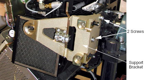
- Remove the two M12 screws from the right front gantry cover
mounting bracket, remove and set aside the bracket.
Figure 1. Support Bracket Removal
- Rotate the Gantry until the HEMIT Tank reaches the 9 o’clock position.
- Cut any tie-wraps.
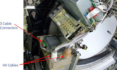
- Use the spanner wrench to remove the high voltage cable connector
from the tank on the power unit.
-
Ground the ends of the H.V. cable to the Gantry frame, to endure no voltage exists at the end of the cable.
-
Use rags or paper towels to wipe excess oil from the H.V. Cable Connector and tank well.
-
Stuff the tank wells with paper towels to absorb any oil.
Figure 2. HV Cable Configuration
-
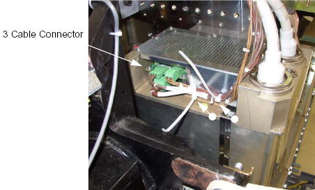
- Cut any tie-wraps.
- Disconnect the 3 cable connector from the HEMIT Tank.
Figure 3. HEMIT Tank Cable Configuration
- Rotate the Gantry until the HEMIT Tank reaches approximately 2 o’clock position.
- Engage gantry rotational lock.
- Remove the HEMIT Tank from the gantry:
- warning
- Attach the hoist to the boom arm in the gantry.
- Attach the hoist lifting chain to the lifting bracket on the HEMIT Tank bottom.
- Remove slack from the hoist chain.
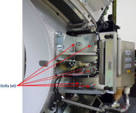
- Remove the 6 bolts that fasten the HEMIT Tank to the rotating
base.
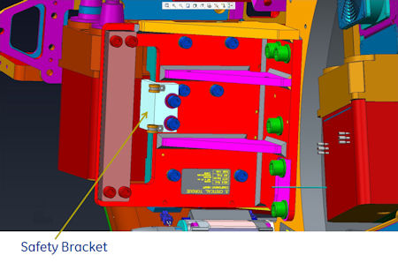
In case of Cj M40, remove 2 bolts that fasten the safety bracket.
Figure 4. Safety Bracket
- Use the hoist to lower the HEMIT Tank to the floor.
Figure 5. HEMIT Tank Removal

2 HEMIT Tank Installation
Procedure
- Ensure that Lockout/Tagout procedure has been applied, and that gantry power is removed.
- Ensure that gantry rotational lock is engaged and gantry does not rotate by attempting to rotate gantry by hand.
- Using the hoist, attach the new HEMIT Tank to gantry.
- Torque the 6 bolts to the following pre-load value.
- Torque the 2 bolts for safety bracket to the following pre-load
value.
- Torque the 8 bolts to the following final value.
- Re-connect all the cables.note: Follow the following procedure for tightening HV cable ring nuts.
- Lightly wet the new rubber quad ring with transformer oil.
- Return the quad ring to its slot at the top of the receptacle retaining ring.
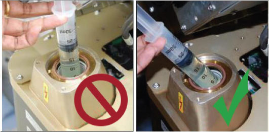
- Pour transformer oil into the receptacle approximately 13 ml (reference only, please adjust the oil amount as necessary).note: DO NOT use the syringe in vertical position, this will result in air bubbles which increase the chances of the high voltage breakdown.
Figure 6. Filling Receptacle
- Align the cable terminal orienting key with the notch in the receptacle.
- Slowly insert the cable, to engage the connector pins, and seat the cable in the receptacle.note:
After installing the cable to the receptacle, confirm the transformer oil is spilled over a little from the receptacle as shown in Figure 7.
If the transformer oil is inappropriate amount, adjust the oil amount as necessary.
Figure 7. Appropriate Amount of Transformer Oil
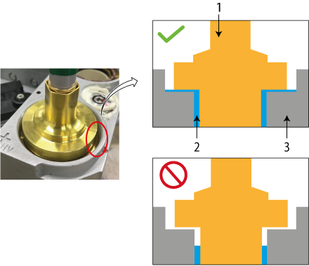
1 HV Cable 2 Transformer Oil 3 Receptacle - Tighten the cable ring nut by ¼ to ½ of a full turn by spanner wrench after the gap is closed and friction is felt by hand.
- Carefully wipe up all excess oil.
3 Finalization
Procedure
- Perform Gantry Rotation Safety Check.
- Perform Gantry Balance Procedure.
- Perform System Scanning Test.note: If HEMIT tank HV instability impacted filament aging, TnT Reset and Filament calibration may be performed. But most of cases, those steps would not be necessary.