- Topic ID: task_ij1_cby_rmb
- Version: 4.0
- Date: Jan 23, 2022 10:48:10 PM
(20HW16.x) Load From Cold
Prerequisites
Overview
The following procedure describes and illustrates the system software loading process commonly referred to as the Load From Cold (LFC). It is important to follow the steps listed below in order.
1 Software Deliverable
Procedure
- Bootable USB Memory with OS/KVM/Application
2 Pre-LFC Checks and Information Gathering
Procedure
- Confirm that the BIOS setting of Boot option is following. Refer to Align, Setup, Calibration > Console > Z8G4 Host PC BIOS Setup and CMOS Battery Replacement.
- USB storage Boot is checked.
- Legacy Boot Order is
- USB Drivers
- CD/DVD Drives
- SATA
- Confirm that a current System State Backup Media is on site. If unsure of the status of the System State, execute System State Save Restore procedure found in the Software Chapter of this manual. Save a System State Backup to either DVD-RAM or USB Media.
- Remove all media from DVD Peripheral Towers before starting the OS Load of the LFC process.
3 Information Capture
3.1 Common Information Capture
Procedure
- Record Autovoice Volume control settings (ALT-F3 by Toolchest, upper right corner).
- Write down all of the system INFO information on the reconfig screens, including the network information.

- notice
- Verify and record specific system hardware configuration.
- Open a shell and type the following:
{ctuser@hostname}cat /usr/g/config/INFO
- Record screen information.
- Open a shell and type the following:
- If the console has Connect Pro installed, write down the information when you run installhisris so it can be entered on the new console when installing the Connect Pro option.
- PPS server information can be confirmed by the following procedure.
- {ctuser@hostname} cd /usr/g/ctuser/nuevo/resources/pps
- {ctuser@hostname}
cat pps_scp.properties
scp.hostname=<Local hostname>
scp.ip=<SCP_IP>
scp.port=<SCP_Port>
scp.calledAeTitle=<SCP_AE_Title>
scu.calledAeTitle=<SCU_AE_Title>
- Close the Service Desktop window in the upper left corner of the screen.
3.2 Information Capture for Option Installation
If your system does NOT have Exam Split option, skip this section. Perform these steps before powering down your current Operator Console:
- Open a Unix Shell and type the following:
- {ctuser@hostname} su -
- Password: #bigguy
- [root@hostname] ls -l ~ctuser/ves/.hesMode
note: There are no spaces in the phrase ~ctuser/ves/.hesMode - Examine the results.
- If the results are similar to:
-rw-r--r-- l ctuser users 0 Apr 3 12:43
/usr/g/ctuser/ves/.hesMode
The HES (Hard Exam Split) mode is configured.
- If the results show 'No such file or directory', then VES (Virtual Exam Split) mode is configured.
- If the results are similar to:
- Record Exam Split Mode (Hard or Virtual). This info will be used during the LFC Options Installation.
- Close the Unix Shell.
4 Backup Edison Information
Procedure
- How to confirm the Smart Subscription is used
- Open command window and type the following command.
{ctuser@host} swokinstall -p <ENTER>
- Make sure that "SmartSubscription -Connection" option is present.
- Open command window and type the following command.
- Check and record the Edison Private Proxy IP address (externalnet-1)Record the EIS IP Address from Titanium Cloud. This will be used at Device Bootstrap setting.
- On CT console, open a shell on CT console, input command to open a browser.
{ctuser@bj66} firefox
- Input weblink in the firefox browser.
https://172.16.0.199/auth/login/
Continue Process if you meet any attention.
- OAM/Titanium dashboard home page display.
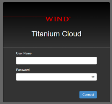
- Input OAM username and password. Connect.
- Select Network -> Floating IPs from the left panel.
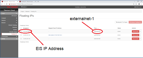
- Recorded the EIS IP Address of external-net1.
Normally, it is 172.16.0.120.
- On CT console, open a shell on CT console, input command to open a browser.
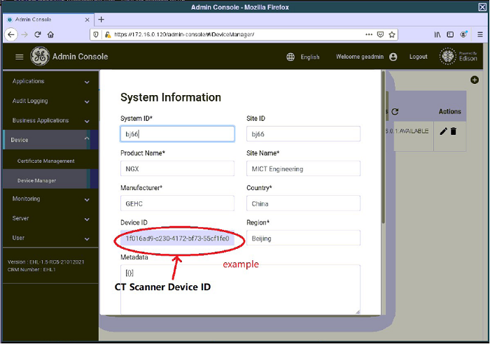
- Check and record the CT Scanner and Device IDRecord the CT Scanner Device ID from Admin Console. This will be also used at Device Bootstrap setting.
- Open a shell on CT console, input command to open a browser.
{ctuser@bj66} firefox
- Input weblink in the firefox browser.
https://172.16.0.120/admin-console-home
*This IP should be consisted with EIS IP address recorded in above step. It is the IP is not 172.16.0.120, please change the link accordingly.
Continue Process if you meet any attention.
- Admin console home page display.
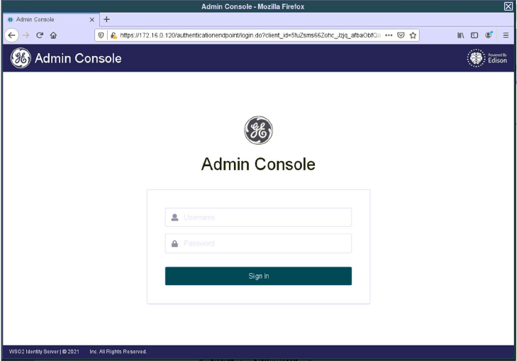
- Input admin console username and password. Sign in.
- Select Device -> Device manager from the left panel. You can see current CT system registered on EHL.
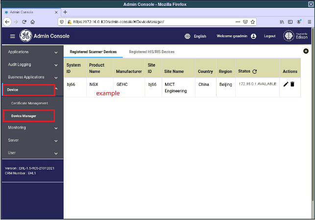
- Click the pen button in “Action” column.
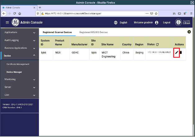
- Record the CT scanner Device ID.
- Click “Cancel” at the bottom of this window to close it.
- Open a shell on CT console, input command to open a browser.
- Delecte the CT User account from the Registered Users ListDelete the CT user account from the Registered Users list of Admin Console. If this is not done, the error occurs at Bootstrap registration.
- In Admin Console, select User -> User Management from the left panel.
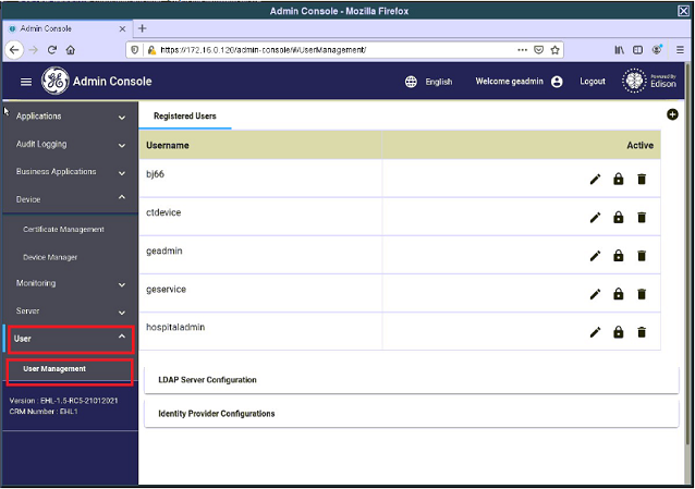
- Delete CT user account from the Registered Users list.
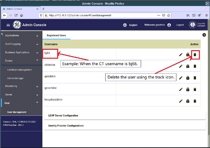 note: If this step do not perform, error will occur at Bootstrap registration afeter LFC.
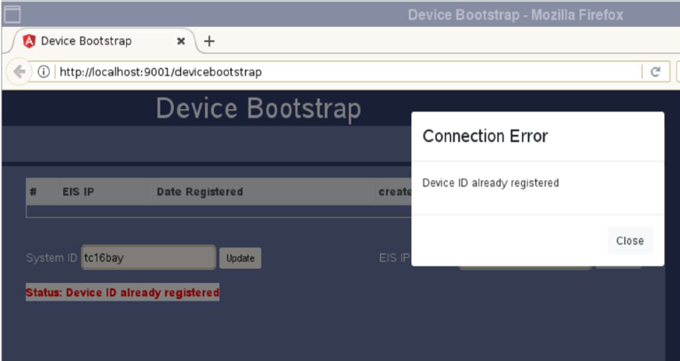
- In Admin Console, select User -> User Management from the left panel.
5 Operating Software (OS) Load
Procedure
- Unplug the Hospital Network cable from rear Console bulkhead.
- Insert Bootable USB Memory with OS/KVM/Application into the Host Computer.
- Shutdown and Power Cycle Operator Console:
- Turn Off Operator Console power. Wait 30 seconds, and then turn power On.
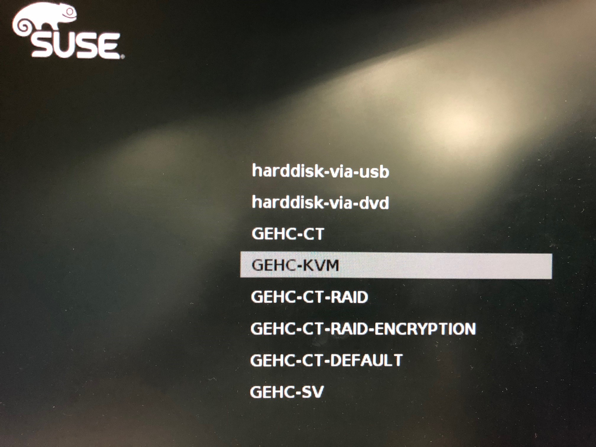
- As the Host Computer restarts, the boot process GUI appears. Select “GEHC - KVM”.
Figure 1. Monitor Display – Boot Process GUI
- During the OS installation, host reboot happens. Wait a moment to complete OS installation
- After the OS is configured on the computer, the KVM Install will start automatically.
- After the KVM is configured on the Host Computer, the Application install will start automatically.note:
Dual Monitor Displays: From this point in the procedure, the only right monitor display will appear, and the left monitor will not appear. This is normal, do not move monitor video cables! This condition will be resolved after the Application Software is loaded on the system.
6 Applications Software (APPS) Load
Procedure
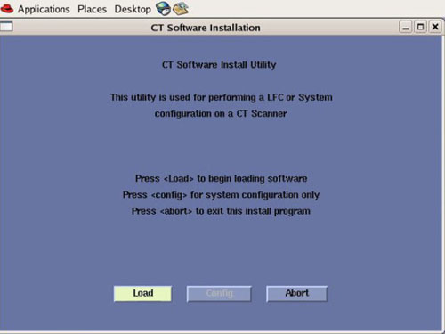
- Select Load in the CT Software Installation window.
Figure 2. Apps Load Command Window
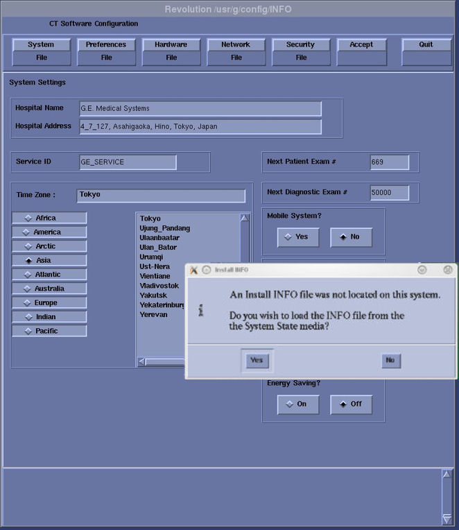
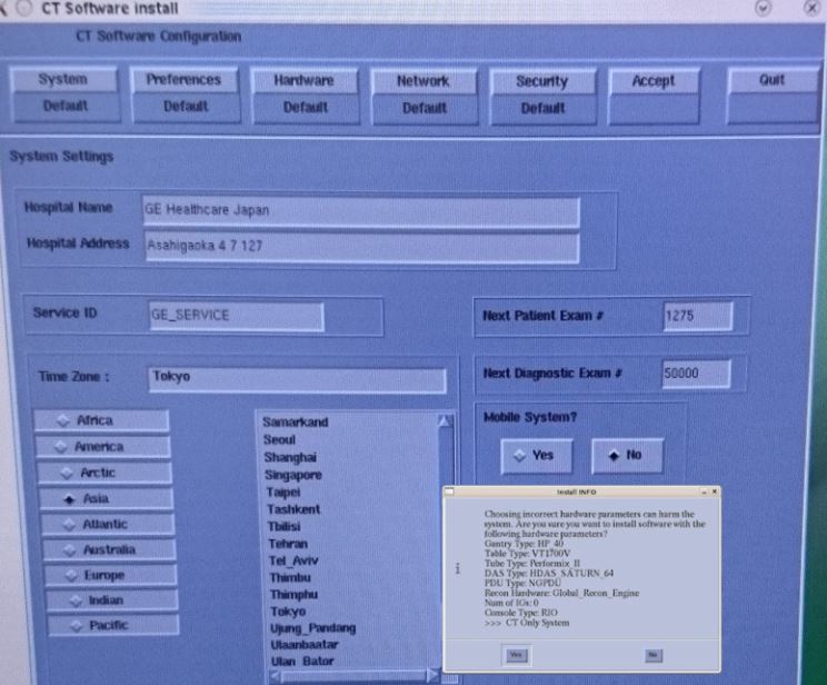
- System State decision for Install INFO decision box will appear.
Select Yes.
Figure 3. Install INFO Window
 note:
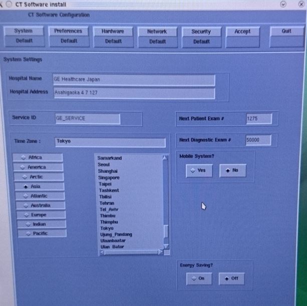
note:If a valid and current System State Backup media is not available or this is a first time install of software, answer [No] and manually configure the Hardware Tab to define System and Console Type in accordance with the procedure Manually Configuring System INFO.
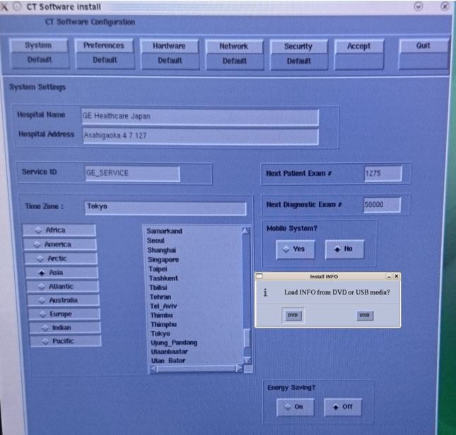
- System State (Install INFO) Media Type decision window will appear.
Select DVD or USB based on media type available.
Figure 4. System State Media Type Window
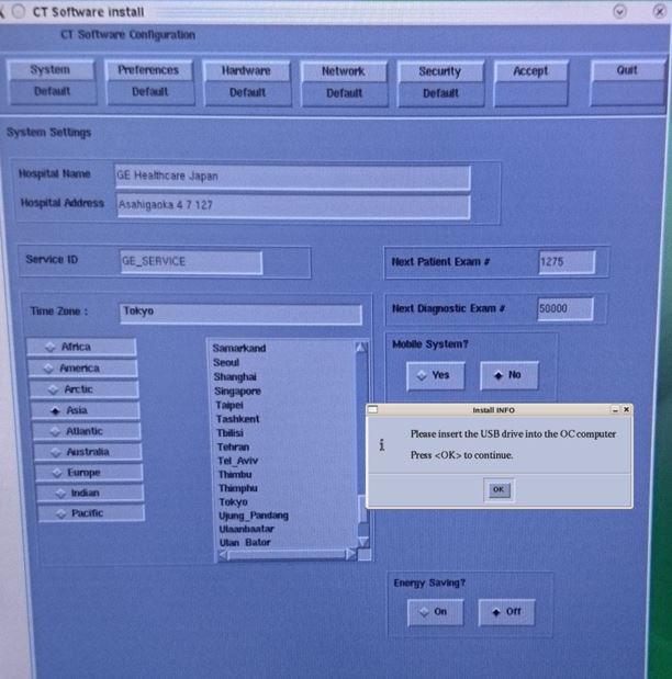
- Insert the System State Backup Media (DVD-RAM or USB).
Select OK.
Figure 5. Install INFO - System State DVD Install Window
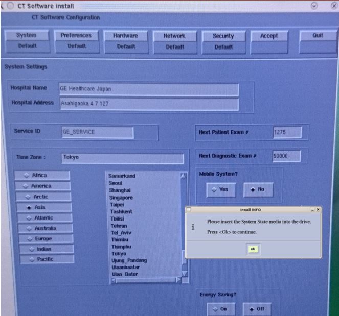
Figure 6. Install INFO - System State USB Install Window
- The Install INFO on the System State Backup Media will be read and if a valid System State Backup has been inserted, an INFO window will become active.
- Check the status of “Change DARC Subnet” setting. If it’s used, execute the followings.
Figure 7. Change DARC Subnet GUI
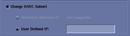
- Record the User defined IP and de-select the Change DARC Subnet check.
- Record the Hospital IP Address and change the IP address which does not conflict with default DARC Subnet address (172.16.xxx.xxx).
The information will be used at end of LFC procedure to revert the updated setting.
- Record the User defined IP and de-select the Change DARC Subnet check.
- Press "Accept" button.
Figure 8. Install INFO - Accept Window
- The Install INFO on the System State Backup Media will be displayed and a confirmation window will appear.
Select Yes.
Figure 9. Install INFO - Confirm Window
 note:
note:Install INFO detail in illustration will differ depending on System type. Verify that the Install INFO detail is correct for the system before selecting [YES].
- System Install INFO will be now used to create the CT Application load routine. Remove Bootable USB Memory with OS/KVM/Application at this timing.note:
Screen saver is working during Application loading and the screen becomes black approx. 4min. with no operation. If it happens, move the mouse to exit the screen save mode. When screen saver works longer time, you may have the login UI When screen saver mode exits. Enter root password at this timing.
note:The screen may have no change more than 2 min. during Application loading. No need to do anything, the process is automatically done, just wait for screen update.
- When completed, the Operator Console will automatically reboot.
- After the Host Computer reboots, a pop-up window will appear.
Figure 10. CT Software Auto-Start Disabled Pop-Up Windows
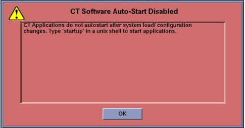
Click OK to close window.
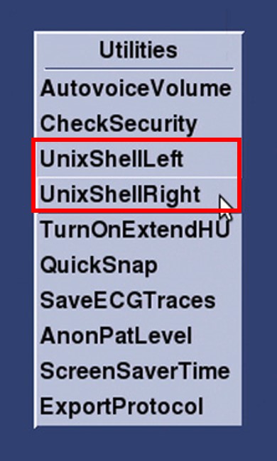
- A blank (Blue) desktop will appear. To continue with LFC, right mouse click anywhere on the blank desktop to display the Tool Chest Utilities Menu and select [UnixShellLeft] or [UnixShellRight].note:
When the left monitor is available, select [UnixShellLeft]. When the right monitor is available, select [UnixShellRight].
Figure 11. Tool Chest - Right Mouse Click on Desktop
 note:
note:Remove System State Backup Media for either DVD-RAM drive or USB port.
7 Service Pack Install
Procedure
- Install Service Pack. Refer to Service Pack Installation Procedure for this software version.
8 LFC Menu - Software Load
Procedure
- Click the right on the mouse, open a Terminal Window, and log on as root:
- Type: {ctuser@hostname} su – [ENTER]
- Type the root password and press [ENTER]
- Type: [root@hostname ~]$ /usr/g/scripts/LFC/startLfcMenu.sh [ENTER]
- A window will be displayed showing the LFC Menu.note:
The LFC Menu Utility provides the tools necessary to complete a LFC process without the use of the Linux Command Line. For more detailed information on the operation of this menu click here: LFC Menu Tutorial.
Figure 12. LFC Menu Window
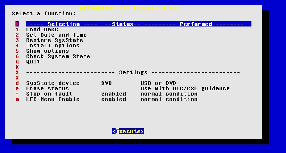
- Load DARC
Select Load DARC (Menu option #1). When DARC software load completed, Click [Close] button at upper left corner and close the DARC load window. Wait for 10 sec for rebooting automatically. If console can’t reboot automatically, reboot it manually. After reboot, execute #1 and #2 steps to restart LFC Menu.
note:Do NOT skip the reboot.
If skipped, the option key installation at Restore State fails.
- Select Set Date and Time (Menu Selection # 2)
Select Execute, the Set Date and Time Utility will open in a shell window.
Follow on screen instructions for setting the correct date and time.
Upon completion of the Set Date and Time Utility, close the shell window to return to the LFC Menu.
- Select Restore System State note:
When this menu selection is chosen, the System State Save and Restore Utility will be launched. See System State Save and Restore procedure in the Software Installation section of the Software Chapter in the Service Documentation for more details.
note: If the system has installed option of Smart Subscription, please see below to Execute Device Bootstrap setup. If not please skip to next Step.Excute Device Bootstrap setup using the information recorded at before.
Refer to the following procedure of Revolution EVO Service Methods.
For EHL 1.3 Installation > Smart Subscription > EHL1.3 > Smart Subscription Feature Connection. Section 4 CT Option Key Install [SmartSubscription -Connection].
For EHL 1.5 Installation > Smart Subscription > EHL1.5 > Smart Subscription Connection. Section 15 CT Option Install [SmartSubscription -Connection].
note: Information for the Smart Subscription -Connection is not restored. Manually enter the information according to Smart Subscription Connection for CT Scanner.Based on options order for each site, install related CT connection options as needed.
DLIR Connection: Refer to the Revolution EVO Service Methods->Installation > Smart Subscription > EHL1.3 > DLIR Feature Connection or Installation > Smart Subscription > EHL1.5 > DLIR Feature Connection
SnapShot Freeze 2.0 Connection: Refer to the Revolution EVO Service Methods ->Installation > Smart Subscription > EHL1.3 > SnapShot Freeze 2.0 Feature Connection or Smart Subscription > EHL1.5 > SnapShot Freeze 2.0 Feature Connection .
AW Server Connection: Refer to the Revolution EVO Service Methods ->Installation > Smart Subscription > EHL1.3 > AW Server Feature Connection or Smart Subscription > EHL1.5 > AW Server Feature Connection.
note:If previously installed, all Options will be restored during the Restore System State.
Insert the System State Media in either the DVD-RAM Drive of USB Port depending on media chosen earlier in this procedure, then select Execute.
A shell window will open and the System Stated will be restored. Several pop-ups will appear requesting configurations settings based on Options being restored. Select appropriate settings for the Options.
Upon completion of the Restore System State, a pop-up will appear reminding that a reboot will be required. Click OK, but do not reboot at this time. Close the shell window to return to the LFC Menu.
- Optional Menu Selectionsnote:
Install Options
If this menu selection is chosen, the Install Software Options Utility will be launched. See Install Software Options procedure in the Software Installation section of the Software Chapter in the Service Documentation for more details. This menu selection is only required when a valid System State is not available. (Valid = Current and Created after Options were loaded on system) If a valid System State was restored in the previous step “Restore System State”, this step may be skipped.
After selecting Execute, a shell window will open and the Install Software Option Utility will be launched. Upon completion of the Install Software Options Utility, a pop-up will appear reminding the user that a reboot will be required. Click OK. Close the shell window to return to the LFC Menu.
note:Show Options
If this menu selection is chosen, the system will display all installed Options. This menu selection should be used to verify that all applicable Options are installed.
After selecting [Execute], a shell window will open and the current installed Options will be displayed. Upon completion of the Show Options, close the shell window to return to the LFC Menu.
note:Check System State
If this menu selection is chosen, the system will display the differences between the INFO file on the System State media to the INFO file on the scanner. Any differences are identified in RED. This selection requires the System State media to be inserted in the applicable device (USB Port or DVD-RAM Drive) prior to executing selection.
After selecting Execute, a shell window will open and the System State Comparison List will be displayed. Upon completion of the Check System State, close the shell window to return to the LFC Menu.
- Select Quit
Then select Execute, the LFC Menu will check that the minimum procedural steps required for a LFC have been completed.
A pop-up window will appear confirming LFC Status.
Click Yes to terminate the LFC Menu.
note:Selecting this menu item will terminate the LFC Menu. Only select this menu selection once all steps have been completed.
Once the LFC Menu is turned off (either by confirming the “Quit” Process selection or by disabling the LFC Menu in the LFC Menu Settings), it will remain disabled. To turn the LFC Menu back on will require the following command string to be entered in a Linux Terminal windows:
Open a Terminal Window, and log on a root.
Type:
[root@hostname] /usr/g/scripts/LFC/startLfcMenu.sh ENTER
- Reboot the System
In the Terminal Windows used to launch the LFC Menu, type:
[root@hostname] reboot ENTER.
9 Tube Install Certification
Procedure
- Set SSA key and perform Check Security on the Tool Chest of Service desktop.
- Close the Common Service Desktop window and switch to ImageWorks desktop. Then, switch back to Service desktop. If the service key is detected, Advanced Service Software Notice window appears. Click on 1, 2 and 3 buttons in order.
- Launch Tube Install Certification on the Common Service Desktop – Configuration Tab. Then, select “GE Medial System Tube” and Confirm button.
- When completed, continue with Flash Download.
10 Flash Download
Procedure
- Perform the Flash Download Utility found on the Common Service Desktop – Utilities Tab, select Flash Download.
Figure 13. Common Service Desktop – Utilities Tab, Flash Download
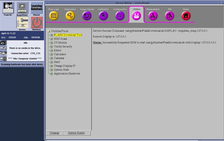 note:
note:The Flash Download takes 5 - 30 minutes, depending on which subsystems need firmware updating.
- When the Flash Download Window opens,
Select Update.
Figure 14. Flash Download Window
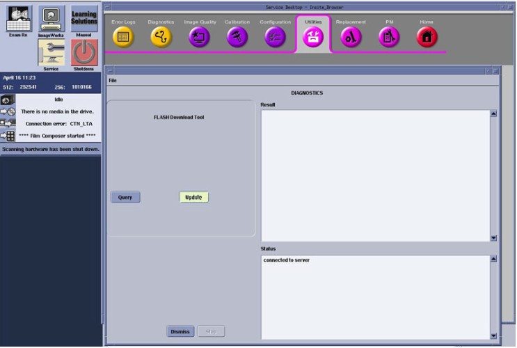
- Once the Gantry Hardware Flash Downloads successfully, select Dismiss.
- Close the Common Service Desktop.
11 Return the Network Information
Procedure
- Open shell window and type "cleanMon" to shut down the CT Application software.
- Type the following to open reconfig screen.
su - <enter>
Enter root password <enter>
# reconfig <enter>
- Press Network tab and set the IP Address and Change DARC Subnet to the original value, recorded at Applications Software (APPS) Load.
- Press Accept button and press “Yes” at pop-up window. System will be rebooted.
- Press “OK” after OS has been started up.
Open shell window and type “st” to start CT application software.
12 Hospital Network Connect
Procedure
- Reconnect the Hospital Network cable at the rear of the Operator Console that was disconnected at the beginning of the LFC.
- Select Shutdown icon on the Desktop and restart the system.
13 InSite Checkout with PNF setting change (If system is connected)
Procedure
- Select “Configure PNF” from Configuration of CSD menu.
- Select “GE Service” and “Edit Rules”.
Figure 15. Edit Rules of PNF
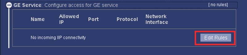
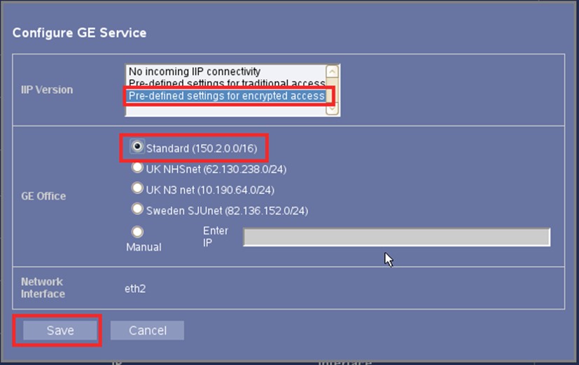
- Select “Pre-defined settings for encrypted access” and “Standard (150.2.0.0/16)”. Then press Save button.note:
GE Office setting may vary depending on the Site environment. Set appropriate setting after InSite checkout if needed.
Figure 16. Setting of Configure Access for GE Service
- If the InSite (and iLinq) was previously used, perform the InSite checkout. New model type (_SUSE_IIP4.5) is required for the checkout.
14 EA3 Enterprise Server Setting
The setting update shall be done for Secured LDAP connection of EA3 Enterprise server.
Execute the following procedure.
Procedure
- Select “Configure EA3” from Configuration tab of CSD menu.
- Select Enterprise tab.
- Select “Simple LDAP”, check “Use SSL” and check “Verify Certificate”. See the following Figure.note:
For “Verify Certificate” to be On, install the LDAP Server Certificate separately in Certificate Management. Certificate Management is available only for ADVANCED and above.
- Set LDAP Server Name in “Server Name/IP”. LDAP Server Name must be configured with not “IP address” but “Domain Name”.
Figure 17. EA3 Enterprise server setting
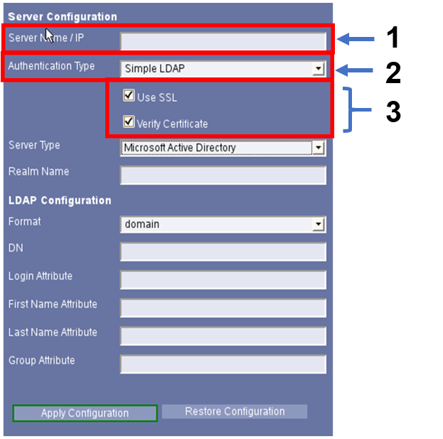
1 Set Domain Name (not IP Address) 2 Select “Simple LDAP” 3 Check both setting.
15 Final Save System State
Procedure
- Perform the System State Save and Restore procedure and save a System State Backup to either DVD-RAM or USB Media.
- Save the System State Backup media in a safe and secure location for future service activity.
16 Finalization
Firewall is set as ON by default after software Load From Cold.
Procedure
- Confirm the PNF settings are correctly restored in [Configure PNF] in Common Service Desktop.
- Confirm if Dynamic Transition software option is correctly installed.
- Open a Terminal window.
- Type: {ctuser@hostname} swokinstall -p[ENTER]
- Confirm that “Dynamic Transition” option is included in the option list.
- Type: {ctuser@hostname} cat /usr/g/config/examRxDisplayMgr.init | grep TRIGGER=1 [ENTER]
- Confirm if “ENABLE_SMART_PREP_AUTO_TRIGGER=1” is included at the output text.
If any output displayed by this command, it means Dynamic Transition option is already installed correctly on the system.
(Example){ctuser@tc13bay}cat /usr/g/config/examRxDisplayMgr.init | grep TRIGGER=1 ENVIRON="CUPIPCREUSEADDR= INIT_INTERVAL_FOR_RD=60000 INIT_INTERVAL_FOR_SNS=60000 SWITCH_LAYOUT_INTERVAL_FOR_RD=150000 INIT_INTERVAL_FOR_AF=60000 SWITCH_LAYOUT_INTERVAL_FOR_AF=60000 INIT_INTERVAL_FOR_AV=60000 SWITCH_LAYOUT_INTERVAL_FOR_AV=60000 IMAGEAVAILSYNC IMAGEAVAILTIMEOUT=200 AFPRIORITY=10 USESCHEDULER=1 NEXTPRIOR_IMAGE_LIMIT=200 NEXTPRIOR_IMAGE_BUFFER_COUNT=20 NEXTPRIOR_SKIP_COUNT=3 LD_LIBRARYN32_PATH=/usr/g/ctuser/display/arch/irix65/lib:/usr/g/ctuser/display/lib32:/usr/g/ctuser/lib32:/usr/lib32:/lib32:/usr/g/informix/lib:/usr/g/informix/lib/esql:/usr/g/ctuser/visibroker/vbc/lib:/usr/g/ctuser/gvtk/arch/irix65/lib LD_LIBRARY_PATH=/usr/g/ctuser/display/arch/linux24-gcc3/lib:/usr/g/ctuser/display/arch/linux24/lib:/usr/g/ctuser/display/lib32:/usr/g/ctuser/lib32:/usr/lib32:/lib32:/usr/g/informix/lib:/usr/g/informix/lib/esql:/usr/g/ctuser/visibroker/vbc/lib:/usr/g/ctuser/gvtk/arch/linux24-gcc3/lib:/usr/g/ctuser/gvtk/arch/linux24/lib:/usr/X11R6/lib GRAPHICRX_DEBUG=1 INIT_INTERVAL_FOR_GRX=60000 AF_VIEWER_OVERRIDE_HAST=1 AF_VIEWER_FILM_RESPONSE_TIME_INT=6000 REALTIME_TIMEOUT=30000 DBX_COMMAND_FILE=/usr/g/ctuser/display/config/display-traceback-gdb.cmd SDC_SELECTION_FILE=/usr/tmp/exam_rx_selection ENABLE_SMART_PREP_AUTO_TRIGGER=1" {ctuser@tc13bay}
- If Dynamic Transition software option is not correctly installed, re-install the option according to the following procedure:
- Launch Install Options from CSD and uninstall “all” option key.
- Reboot the system.
- Launch System State (or System State – USB) from CSD and select [Reconfig Info], then perform Restore System State from System State media.
- Option restoration process will be started.
- Verify that the Dynamic Transition software option is correctly restored per the following steps:
- Open a Unix shell.
- Type: {ctuser@hostname} cat /usr/g/config/examRxDisplayMgr.init | grep TRIGGER=1 [ENTER]
- Confirm that “ENABLE_SMART_PREP_AUTO_TRIGGER=1” is displayed at the end of output.
- Perform Save System State (select [All] button).
- Save the System State Backup media in a safe and secure location for future service activity
- Perform System Scanning Tests in the Functional Checks chapter of this manual to confirm proper operation.