- Topic ID: id_15460915
- Version: 3.0
- Date: Sep 30, 2019 9:29:55 PM
HP xw8400 Lower Level FRU Replacement
Prerequisites
Overview
This procedure describes and illustrates the steps necessary to replace lower level FRUs in the HP xw8400 Host PC.
Lower Level FRUs Supported:
-
CMOS Battery
-
Memory Modules
-
Hard Disk Drives (HDDs)
-
DVD Optical Drive
This procedure only applies to HP xw8400 model computer. Swapping components between an HP xw8000, xw8200, or xw8400 is not allowed.
1 Powering Off (Shutting Down) the Operator Console
Procedure
- Select one of the following methods to Power Off the Operator
Console:
-
If Applications are running, click Shut Down on the desktop and select the Shutdown option.
-
If Applications are down, open a Unix Shell using the Toolchest and type: {ctuser@hostname} halt Enter.
The Operator Console monitor will display a “System Halted” message when it is acceptable to power off the Operator Console.
-
- Power OFF the Operator Console at the front panel switch.
- Make sure to follow all Lockout/Tagout requirements while performing
this procedure. Refer to Equipment Service - Lockout-Tagout-PPE procedure.
For added protection, disconnect the Twist-N-Lock Main Power Cable
from rear of console.
2 Removing the HP xw8400 Host Computer from Operator Console
Procedure
- Remove the front and rear Operator Console covers.
- Remove the cable connections to the HP xw8400 Host Computer
chassis.note:
Verify that all cables are labeled and clearly marked. If necessary, add a label for clarity.
- Remove the power cord at the rear of the Host Computer chassis.
- Remove the four (4) 5mm socket cap mounting screws from the front of the Host Computer, holding the computer to the Operator Console.
- Slide the Host Computer forward (out the front of console) and
set aside.
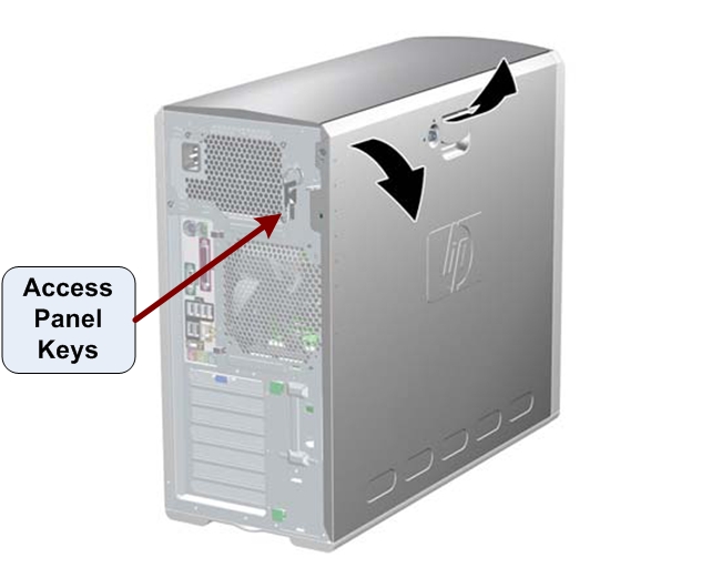
3 Access Panel Removal
Procedure
- If necessary, unlock the access panel using the keys located in the rear of the workstation. See Figure 1
- Once unlocked, pull up on the handle and lift off the access
panel cover.
Figure 1. Access Panel Cover Removal
4 Replacing HP xw8400 Host Computer Lower Level FRUs
4.1 CMOS Battery Replacement
Procedure
- Follow the steps in HP xw8000 Series CMOS Battery Replacement for replacing CMOS Battery in the HP xw8400 Host Computer.
- Continue with Reinstalling the HP xw8400 Host Computer in Operator Console of this document.
4.2 Memory Module Replacement
Procedure
- Follow the steps in HP xw8400 Memory Module Replacement for replacing Memory Modules in the HP xw8400 Host Computer.
- Continue with Reinstalling the HP xw8400 Host Computer in Operator Console of this document.
4.3 Hard Disk Drive (HDD) Replacement
Procedure
- Follow the steps in HP xw8400 Hard Drive Replacement for replacing Hard Disk Drive in the HP xw8400 Host Computer.
- Continue with Reinstalling the HP xw8400 Host Computer in Operator Console of this document.
4.4 DVD Optical Drive Replacement
Procedure
- Follow the steps in for replacing DVD Drive in the HP xw8400 Host Computer.
- Continue with Reinstalling the HP xw8400 Host Computer in Operator Console of this document.
5 Reinstalling the HP xw8400 Host Computer in Operator Console
Procedure
- Slide the HP xw8400 Host Computer into the Operator Console from the front.
- Replace the four (4) 5mm socket cap mounting screws to secure the Host Computer chassis to the Operator Console right side compartment. Torque to 4.6 N-m.
- Mount the power cord to the rear of the Host Computer chassis.
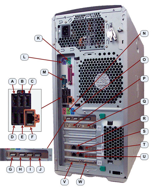
- Replace the rear cable connections.
Figure 2. HP xw8400 Cable Connections
6 Powering-On the Operator Console
Procedure
- Reconnect the Twist-N-Lock Main Power Cable from rear of console and remove Lockout Tagout protection applied earlier.
- Power ON the Operator Console at the console’s front panel switch.
- Visually verify that the Host Computer front panel Power LED
is illuminated. If not, press the Host Computer front panel power
switch to apply power to the Host Computer.
7 Action Required After Hard Disk Drive Replacement
Skip this section if just a memory module was replaced.
Procedure
- If the OS Disk HDD was replaced, it will be necessary to perform
a Load From Cold (LFC) to reinstall Host OS and Application Software.
Follow appropriate LFC procedure for the system on which this HDD
is installed. Follow recommend Finalization steps in the LFC procedure.note:
The LFC procedure will erase and recreate the Image Database located on the Image HDDs.
- If the Image Disk HDD was replaced, it is necessary to perform
the following Image Database Reset procedure to format, partition,
and create the logical disk:
- Reboot the operator console by clicking Shutdown and selecting Restart option.
- Just after the Operating System finishes loading and before
Applications start, click Cancel in the Application Startup window to stop Applications from loading.note:
Applications cannot be running when performing this procedure.
- Open a Terminal Window using the Toolchest and type: {ctuser@hostname} su – Enter.
- Type the root password and press Enter.
- Launch the Host Computer Image Database Reset utility by typing:
[root@hostname] resetImageDB_Linux Enter.note:
The Terminal Window updates, warning the User that all images stored in the Image Database on the Host Computer will be deleted. It then asks the User to either type “YES” to continue with the reset of database; or, to abort the script, to close the Terminal Window or press Enter.
- Continue with the Image Database Reset procedure by typing:
[root@hostname] YES Enter.note:
Must be all capital letters.
- The script deletes any images found, partitions the Image Disks, recreates the CT Image Database, and for PET/CT systems it also recreates the PET Image Database.
- Add restart applications by typing: [root@hostname] st Enter.
8 Finalization
Procedure
- Execute a few test scans and verify that the image(s) reconstruct and are displayed.
- Check that all customer functions are operational. (Auto voice, filming, network, archive).
- Reinstall Console Front and Rear Covers.