- Topic ID: id_15460263
- Version: 6.0
- Date: May 23, 2022 2:13:53 AM
FRDM Replacement Procedure
Prerequisites
Overview
This procedure must be followed in order of the steps given to avoid potential hardware damage to the detector and to have the highest chance. There are a number of detector types and different FRU’s dependent on slot location in each detector. The diagrams below along with the replacement parts list in this procedure can help make sure the right part is used in the right location.
Figure 1. VDAS32 - Sherlock 32 slice Detector
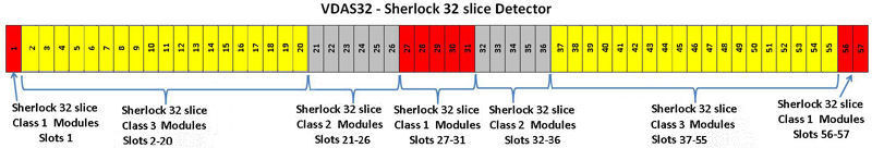
Figure 2. VDAS64 - 64 slice Sherlock Detector
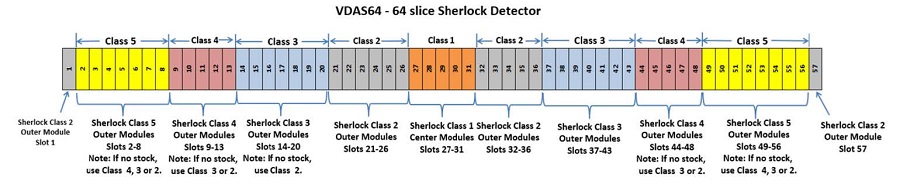
Figure 3. HDAS64 - HALO Detector
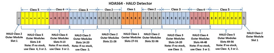
Figure 4. HDAS_Saturn and SDDAS_Saturn_64 = Saturn Detector
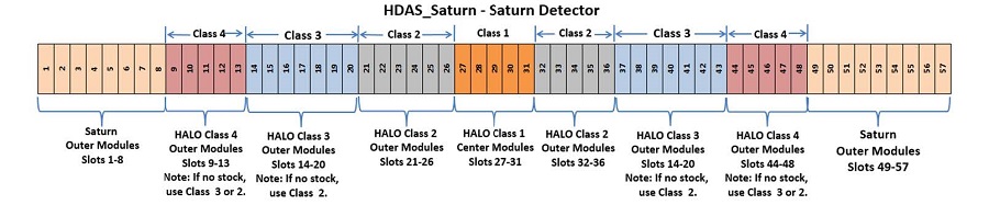
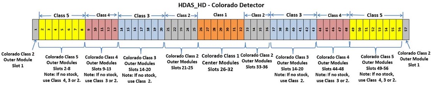
Figure 5. HDAS_HD - Colorado Detector
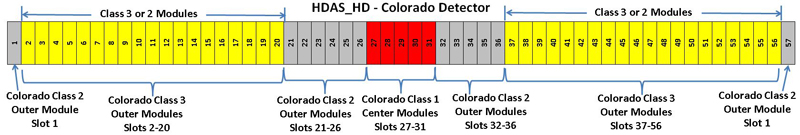
Figure 6. HDAS_HD - Colorado Detector
Replacement Parts below marked as “CHINA ONLY” are only available in China due to regulatory requirements.
1 Special Tools overview
Procedure
-
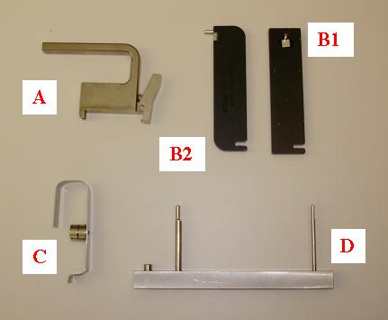
Figure 7 shows the special tools shipped with the new
module with the exception of the handle. The handle was only shipped
with and used on the original VDAS systems. All new modules come with
a built in handle.
Figure 7. Special Tools
-
The Handle (Older VDAS detectors) is attached to the heat sink of the module to aid in removal and installation. The heat sink and digital screws can be used to lift the module out if the handle is not available. Newer modules may come with built in handles on the heatsink.
-
The Controlled Seating Tool is used while installing a module to make sure the alignment pins on the module are centered on the detector collimator to avoid any damage to the detector collimator plates during module insertion. There are two different tools for this application. The wider tool is used for the HDAS_SATURN_64 modules 1-8 and 49-57 and the VCT32 modules.
-
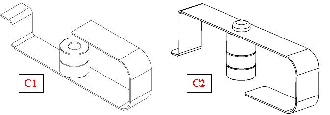
The Bias tool is attached via magnet to the detector rail after seating the new module. The Bias tool pushes the module against the back detector rail with a known force for proper alignment while the module screws are being torqued. There are two slightly different tools for this application. Refer to Figure 8 to understand which tool to use.
-
The Multi-tool is used to aid in clamping the wedge lock after insertion using the notch on one end and for removing light seal clips using the pin on the other end. Different versions of the tool exist but all look very similar and have the same functionality.
Figure 8. Bias tool reference
-
2 Preparing the System
Procedure
- If replacing a center module (slots 27-31) perform the following steps. Otherwise go to step 2.
- From a C-shell type enableBISfeature . If this has already been done in the past, the message will indicate that this function is already enabled.
- If the system did not indicate that the feature was already enabled then a console reboot is necessary to put the change into effect.
- At the console start the FRDM Wizard from
the Common Service Desktop Replacement tab.Figure 9 shows the main screen.
Figure 9. Process Tool
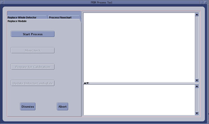
- Select the Replace Module tab and then Start Process. This will set up any necessary preconditions needed in the system software to prepare for a detector module replacement. The physical module replacement can now be performed.
- Move the table full back out of the gantry and move it full down to allow you to completely move the front cover away from the gantry.
- Stop the rotor of X-ray tube in case of Liquid Bearing Tube before HVDC off. Refer to Liquid Bearing Tube Rotor stop procedure for details.
- Remove the right side gantry cover and disable Axial Drive and
HVDC from the service switch panel.
Refer to
- Position the detector at 12 o'clock and lock gantry rotation.
- Shut down all gantry power from the service switch panel.
- Remove the side, top and front gantry covers. The rear cover needs to be released and moved back slightly to allow easy access to the back detector rail.
- Reconnect the front cover display and keypad and turn power on to the gantry to allow the table to be moved to full up position to use as a work table. Then power down the gantry again.
- Cover the Tube Collimator port to protect it against dropped tools or screws. (Cloth or any other available item)
3 Air Plenum Removal
Procedure
- Remove the Detector Air Plenum as shown in Detector Air Plenum Removal/Installation.note:
Reminder that using the mouse right button on the above document link and selecting “Open in new Window” will keep this document open at the same time for ease in use. Can leave the Air Plenum instructions open for later use when reinstalling the plenum.
4 FRDM Removal
Procedure
- Make sure ESD strap is in use prior to continuing.note:
The order of the following steps is critical to success. Do NOT change the order. Read each step and cautions completely prior to performing that step.
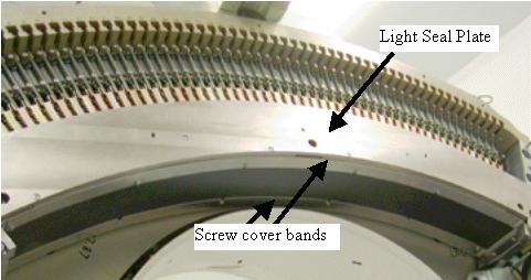
- Remove cover band end screws (not captive) and loosen 4 middle
screws, then slide off the screw cover bands. See Figure 10. Remove the middle screws if needed, the cover bands are slotted
in the middle.note:
If any of the cover band screws are right next to the screw holes for the module being replaced, those screws will need to be removed so they don't interfere with the module seating tool used during module installation.
Figure 10. Screw Cover Bands
- Remove torx screws (not captive) on the light seal plate with
the supplied bit, then lift off the light seal plate. See Figure 11.note:
If the detector does not have torx screws on the light seal plate, the use a hex wrench to remove the screws. Replace with torx screws supplied with the replacement module during reassembly. Early detectors had hex head screws that will deform with usage.
Figure 11. Light Seal Plate
- Put on gloves (supplied with system) before continuing to avoid introducing any contaminates on the detector module or around the detector collimator.
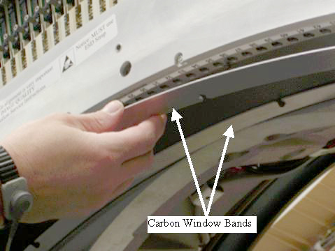
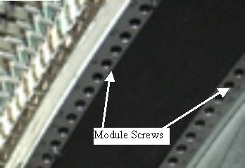
- Remove module screws on either side of carbon window for the
module being replaced. See Figure 12.
Figure 12. Module Screws
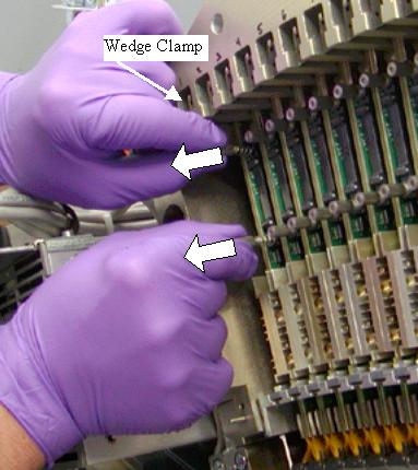
- Completely loosen the digital cable thumb screws until they
pull back freely from the backplane. Do NOT release the wedge clamp yet. See Figure 13.
Figure 13. Digital Screws and Wedge Clamp
- Pull both cable screws away from the backplane approximately 3/8” (8mm) to release the cable edge card connector from the backplane.
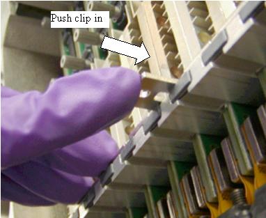
- Remove the light seal clip on each side of the module. Use the
Multi-Tool supplied as shown in Figure 14. There are two different designs for this tool (see Figure 7)note:
Early 64 slice Sherlock (VDAS64) detectors and all 32 slice detectors manufactured before JULY 2009 did not have light seal clips so this step can be skipped if the clips are not installed.
-
Insert the MultiTool pin into the Light Seal clip hole, tilt the tool up to pull clip out then pull straight out to finish removing clip.
-
Tool has a magnet to keep metal clips from falling into gantry during removal. The newer clips are plastic, so make sure to catch these clips during removal, as the magnetic tool will have no effect.
Figure 14. Light Seal Clip Removal
-
- Release and remove the wedge clamp.note:
Releasing the wedge clamp prior to disconnecting the digital cable from the backplane can damage the digital cable screws or the backplane connector.
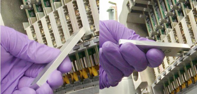
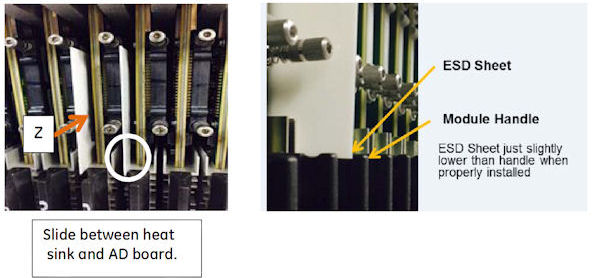
- Slide the ESD plastic sheet between the AD board and heat sink,
along the Z direction, as shown in the left illustration in Figure 16. If module
is between two modules, two ESD plastic sheets are required, one in
front and one in back of module as shown.
If necessary, gently wiggle the sheet while inserting to place as far into the detector as possible, but do not force the sheet in place with excessive pressure.
The ESD plastic sheet should be just slightly below module handle when properly inserted.
Figure 15. ESD Plastic Sheet
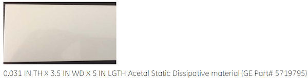
Figure 16. Usage of ESD Plastic Sheet
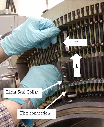
- Hold onto the module built in black handle and one of the digital
cable screws. Lift the module up until the Light seal collar completely
clears the brackets it is resting between then slide it out. See Figure 17 and Figure 18.
-
Module alignment notches on the Light seal collar and the pins at the other end of the board must clear the alignment slots to allow the module to slide out of the detector.
-
A digital cable screw can be held with the other hand to aid in guiding the module up and out if needed.
-
If the module does not seem to move up, check the digital cable. Make sure it is released from the backplane.
-
If the module seems to be stuck to the rail such that the flex connections are pulling up when the entire assembly is lifted up, STOP. Completely insert the Controlled Seating Tool (seen in Figure 21) into the detector rails for that module. This will keep the module from hitting the detector collimator plates while you gently push up with a finger on the detector module front edge to release it from the detector rails. Remove the seating tool and continue to remove the module from the detector.
Figure 17. Module Removal
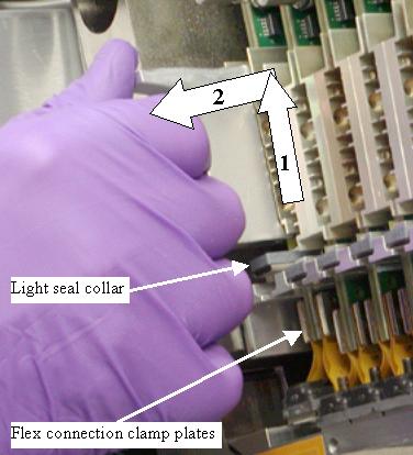
Figure 18. Module Alignment Pins
 note:
note:After removing the module avoid touching the flex connection or detector module face. Hold the module by the heat sink or metal bracket on the opposite end of the of the assembly.
-
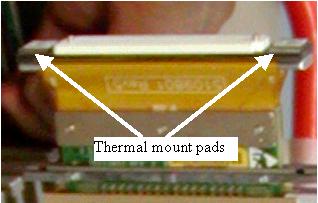
- After removing the module visually inspect the detector rails
to see if any Thermal Mount pads from the detector module were left
(Some early modules had this problem). The module front end can also
be inspected to see if both side pads are still in place. See Figure 19. The pads are seen as thin white squares on the plates that the
mounting screws go through. Carefully remove any pads left on the
rails without touching the detector collimator plates. Any damage
to the collimator plates will require full detector replacement. Procedure VCT Detector Thermal pad Removal must be used
to remove any thermal pads.
Figure 19. Detector Module Front End
- If the initial problem was an Open Pixel, first check the torque
on the module flex screws before installing a new module using the
following steps. These steps require a Torx T10 size driver bit and
the torque driver. Loose flex screws are typically the problem for
any open pixel issue. Resolution will be known before any calibrations
are run.
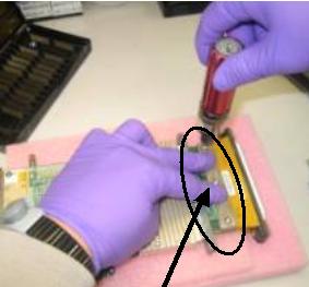
- Torque the 3 flex connection screws to the following setting
starting with the center screw.
Figure 20. Flex Connection Screws
- Install Module as shown in the next sections and run maratio’s test from DASTools to see if problem has been resolved.
- If the problem was not resolved, install new module
- Torque the 3 flex connection screws to the following setting
starting with the center screw.
- If a center set (5 matched modules) is being used repeat this section for all 5 center modules in slots 27 - 31.
5 FRDM Installation
Procedure
- The order of the following steps is critical to success. Do NOT change the order. Read each step and cautions completely
prior to performing that step.note:
Do not touch the detector module face or flex connections. Handle the module by the heat sink, black handle, or metal bracket on the opposite end of the assembly.
note:If replacement is a center set (5 matched modules) in slots 27 - 31, make sure you install the new center modules in the slot location marked on the new modules. Example, new module marked as slot 27 MUST be installed in detector slot location 27. Repeat the module installation steps for each of the 5 center modules.
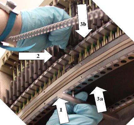
- Install the new module using the following order of steps. (See Figure 21 for illustrated
process with numbered references)
- With one hand, insert the Controlled Seating Tool part way (1) so pins do not extend above detector rails to avoid scratching the detector module during insertion. Putting your thumb between the tool and the detector can help control the tool insertion while you insert the module.
- Slide the ESD plastic sheet between the AD board and heat sink,
along the Z direction, as shown in the left illustration in Figure 16. If module
is between two modules, two ESD plastic sheets are required, one in
front and one in back of module as shown.
The ESD plastic sheet should be just slightly below module handle when properly inserted.
- With the other hand, insert the Module in (2) toward backplane
using the black handle.
The Detector light seal brackets must be between the module flex connection plates and module light seal plate as shown in Figure 18 to allow module to slide into detector.
- Push the Controlled Seating Tool completely up into detector rails (3a) then lower module down (3b) on top of the seating tool so that the module screw holes engage the seating tool. This will ensure that the module alignment pins do not hit the detector collimator plates during module insertion.
Notes:
-
The module must be seated on the detector rail. DO NOT force it into position. The module will seat on the rail when the module alignment pins are properly aligned.
-
You may have to push the top of the board toward the backplane to engage the top alignment pins if the digital cable is pushing the board away from the backplane.
-
If the Controlled Seating Tool is not used, detector collimator damage may result resulting in outer row image quality issues.
Figure 21. Module Insertion
- Remove the seating tool only after the module is seated on the detector rails.
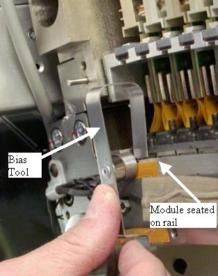
- Attach the bias tool to the detector rail to push the module
against the back detector rail with a known force. See Figure 22. The SATURN_64_HD detector requires a slightly different bias tool,
which is shown in C2 of Figure 8. Gloves can be removed at this point.
Figure 22. Bias Tool
- Insert both module screws on either side of the carbon window
and torque to the value shown in Table 7. Torque the back screw first.note:
Do NOT push up on the module screws. Pushing up may unseat the module and damage the detector collimator plates when the screws are tightened.

 caution
- Remove the bias tool from the detector rail.
- Insert the wedge clamp and lock it. (Orientation: Plate of the
wedge clamp against the board)
Figure 23. Wedge Clamp Insertion
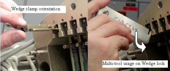
- After locking the wedge clamp, carefully install and finger
tighten both digital cable thumb screws using the process below to
help avoid cross threading. The screws will go in easy when properly
aligned.
- Pull the digital cable screws away from the backplane initially and then in toward backplane to help initial connector alignment. Use a flashlight if necessary to see if the connector is aligned to the backplane socket. A “click” can be heard when you set down the screws indicating the screws have hit the backplane threaded socket.
- Rotate the screws counter clockwise to hear a clicking sound made by the threads of the screw and threads of the socket. This will insure that the screws are lined up to the connector prior to threading them in.
- Start both screws into the sockets. Thread both screws in together so the cable edge connector is pulled into the backplane straight. Stop and back out the screws if any squeak is heard as this indicates cross threading. Try rotating the screws counter clockwise until you hear a second “click”. This can help if the screw was previously cross threaded to avoid the crossed threads.
- May need to carefully pull the digital cable screws to one side to help alignment if needed while performing steps a-c above.
- Torque the screws per Table 8.
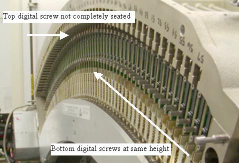
- Look across the modules from the side to make sure the digital
cable screws are seated to the same height as the rest of the modules.
This will indicate proper connection. SeeFigure 24 for example side view. Note a top screw may not be fully seated
in this view. Bottom screws all appear at same height.
Figure 24. Module Screws Side View
- Insert the light seal clips on either side of the module (for
all modules replaced). See Figure 25.
Figure 25. Light Seal Clip Insertion
- Suggested but not Mandatory: Use the Deionizing fan to remove any static buildup during the replacement process. Hold the fan within 2 feet of the replaced module for 60 seconds.
- Visually inspect the light seal plate for any hair or other debris. Wipe clean prior to installation to avoid getting debris inside detector.
- Install the light seal cover being careful around thermistor
wires, using torx head screws. Torque screws to the value shown in Table 9.
- Install the screw cover bands (both bands are identical) and
torque the screws to the value shown in Table 10.note:
The end screws on the screw cover band next to the rotating base frame can not be reached with the torque driver. Just snug them carefully with an offset hex wrench. Do not overtighten.
6 Plenum Installation
Procedure
- Install the air plenum as shown in Detector Air Plenum Removal/Installation.
- Install the gantry rear cover.
- Connect the front cover cabling but do not install the front cover until after checking module alignments and DAStools tests. The display is required to be connected for the test scans.
- Turn on the gantry power from the service switch panel leaving
HVDC and Axial drive disabled.
Note the current time. It will take the detector approximately 45 minutes to warm up to operating temperature from the time power is turned on. The alignment and DAStools tests can be run during the warm-up time but calibrations can not be started until the detector is up to temperature.
- Release the gantry rotational lock and make sure gantry is ready for rotation.
- Enable axial drive and HVDC from the service switch panel.
7 Detector testing
Procedure
- From the FRDM Process Tool currently open
at the console select Minicheck and acknowledge
the pop up window if the gantry is ready to rotate.note:
The Wizard will first read the HART data from all detector modules. This will take less than 60 seconds. If this process takes longer, then the communication path to the detector has locked up. Abort the FRDM Wizard, reset the gantry power or perform a scan hardware reset, then restart the Wizard and try again.
The alignment check will start after the scan button is pressed when prompted. (Non-rotating scan)
If needed later, The alignment check can also be run from a Unix Shell. Open a Unix shell and type the following command: zalignmentWizard
- The alignment check will run 2 scans and show plots as shown
in Figure 26. Processing will take approximately 2 minutes
after the scans are run. note:
The plot window must be closed using the File menu before DASTools GUI will open.
Figure 26. Alignment Check Display
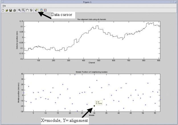
- Check the bottom graph to make sure the module is within specifications
defined by Table 11. Use the following guidelines for looking at the plots.
- The plots autoscale to fit the data. First look at the Y-scale of the bottom plot. If the upper and lower values are at or less than the specification, then all points in the plot are within specification.
- Module 1 and 57 are plotted on the very edge of the plots. In the example of Figure 26, Module 1 can be found at +5 just above the zero mark. Module 57 can be found at -8 on the right side edge of the plot.
- For any questionable plot point, select Data Cursor from the top tool bar and then use the mouse cursor to select the module “+” on the bottom graph. A small window will appear showing the module number and plot value. For example module 30 in Figure 26 is shown to be at -19.
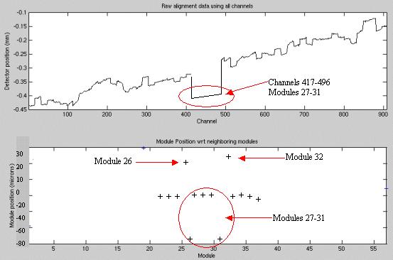
- If more than two side by side modules are replaced at once an
out of alignment condition can occur if none of the modules were aligned
with the bias tool. This signature is different than any single module.
See Figure 27.
All 5 modules are out of alignment with the rest of the detector as seen on the top graph, yet modules 26, 27, 31, and 32 show out of alignment. This is further explained in the alignment wizard user instructions. Note this potential condition and see that it is the center 5 modules that all need to be repositioned as shown in the top graph. Modules 26 and 32 are effected due to the common edge with modules 27 and 31 and will show better results after the center set is repositioned.
Figure 27. Center Module Offset Example
See zalignmentWizard User Instructions for more details if needed.
- If the module alignment check does not pass; perform the following:
- Reopen the Detector following all previous cautions and steps
in Air Plenum Removal and FRDM Removal loosening module screws without
actually removing them to allow module realignment.note:
If you are working with one of the center 5 modules (27-31), try to reposition the module using the bias tool once. If the module does not align properly follow the special instructions in the Center Module Alignment Procedure to perform special manual alignment.
- Always use the bias tool to push the module toward the back rail. After the bias tool is installed, torque the module screws to the value shown in Table 7.
- Re-assemble the system per Plenum Installation.
- Exit the plot from the previous alignment scan using the File menu (do not minimize the window), Dismiss the DASTools GUI that shows up and select MiniCheck again to rerun the alignment wizard test. Rerun the module alignment check to verify proper alignment, perform this step again if alignment is still not passing.
- Reopen the Detector following all previous cautions and steps
in Air Plenum Removal and FRDM Removal loosening module screws without
actually removing them to allow module realignment.
- After the alignment plot is closed (not minimized, must exit
the window) the DASTools GUI will automatically show up. From the DASTools interface run the following rotating tests.
- Select and Run mA Ratio Test (creates/updates the bad channel map)
- Select and Run the Auto Test from DASTools.
- If all the checks pass continue with the next step. If anything fails, troubleshoot per the failed test.
- Perform any desired quick checks if problem was not a digital issue that was already verified by the mini check tests.
8 Gantry Reassembly
Procedure
- Install all gantry covers remembering to enable Axial Drive
just before installing gantry right side cover.
Refer to
note:Gantry covers MUST be in place and detector up to proper temperature prior to running full calibration.
9 System Calibration
Procedure
- The user message log will indicate when the detector temperature has reached specification by a message indicating the detector has returned to normal temperature. You may have to wait for up to 45 minutes from the time the detector was powered on to allow detector to warm up prior to starting the calibration process. Calibrations are not allowed to start until the detector reaches proper temperature.
- From the FRDM Process Tool currently open
at the console select Prep for Calibrations.
A test will be run prior to calibrations that will check for center artifacts. This test is specific for center module (27-31) and will only be run when a center module is replaced to make sure no center module artifacts have been introduced due to accidental movement of a center module. Acknowledge that the system is ready for gantry rotation and then press the Start Scan hard key when indicated to run the test.
The Center module test will report a Pass or Fail. If the center check fails, the center module just inserted is not compatible with the other center modules and needs to be replaced. A failure will not be a common occurrence since the system has been updated with a new calibration vector to account for center module variations. Only significant module issues should cause a failure. Potential IQ issues for a failing module include all center related artifacts including center spot and smudge. If the test passes, continue with calibrations.
- Perform a Collimator Cal.
- Perform a full Detailed Cal.
- After the above calibrations a Fastcal must also be run from Daily Prep to complete the updates to the calibrations. (This is new with the VCT system)
10 Finalization
Procedure
- Perform the Quality Assurance Test.
- Perform a Save State to save the new calibration data.
- From the FRDM Process Tool currently open at the console select Update Detector Configuration when the system is ready for customer operation. This will read and update the new detector configuration and perform any background cleanup of temporary software files created by the tool during the replacement process.
- Fill out the VCT Digital Module Return Form included with the module or online. This information is important for root cause analysis of failed parts to improve quality of processes and future parts. This also helps clarify any issue reported that would not have been found by normal retests that could result in a No Defect Found.
- Return all tools and equipment sent with module along with the
replaced module(s).
Tools Return Policy
Re-package all provided service tools, in the original packages, and place into the FRU shipping container. Failure to return these items will result in your Service Contract being billed the significant cost of these tools.
-
Controlled Seating Tool
-
Bias Tool
-
Multi-tool
-
Torx T-20 driver bit
-