- Topic ID: id_15460181
- Version: 3.0
- Date: Dec 28, 2021 10:07:51 PM
Detector Air Plenum Removal and Installation (Non-M40)
Prerequisites
Overview
This procedure defines the necessary steps to Remove and Install the Detector Air Plenum Assembly.
1 Initial Steps if covers and power have not already been removed
Procedure
 danger
- Remove right side gantry cover.
Refer to
- Stop the rotor of X-ray tube in case of Liquid Bearing Tube before HVDC off. Refer to Liquid Bearing Tube Rotor stop procedure for details.
- Disable Axial Drive and HVDC on the service switch panel.
- Position the Detector at 12 o'clock and lock gantry rotation.
- Turn off the 120 VAC service switch from the service switch panel.
- Remove the gantry front cover.
2 Removal Procedures
Procedure
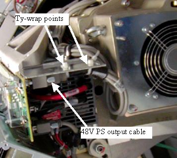
- Disconnect the 48V Power supply output cable to be able to move
the cable bundle out of the way for easier plenum removal. See Figure 1.note:
With the 2006 Style plenum, the 48V cable routing allows easy plenum removal without needing to remove the 48V cable. Only remove cable if you think it is necessary.
Figure 1. 48V Power Supply Cable
- If another person is available to help, skip the next step (removing fan plate) and just remove the plenum with fan plate in place.
- Remove the fan plate by removing the fan cabling (5 fan control
lines) and loosening the 12 captive screws holding the fan plate to
the Air plenum. See Figure 2 for VCT Detector front view.
Figure 2. VCT Detector Front View (2005 Style Plenum)
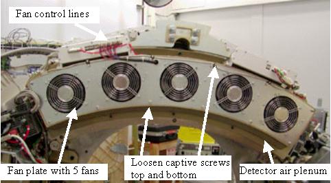
Figure 3. 2006 Style Plenum with Cable Covers
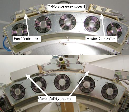
- From the CFC (Fan controller on the left of the plenum) disconnect cabling on the front coming from the detector.
- From the DHC (Heater Controller on the right of the plenum) disconnect cabling on the front coming from the detector. (Cables also on backside for 2005 style plenum.)
- Loosen the 8 captive plenum screws, 3 bottom, 3 top, 1 on each side. Newer plenums may have only 2 screws on the bottom.
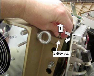
- Pull up on safety pin small knob and rotate ¼ turn to
keep the safety pin disengaged. (on both sides of plenum) See Figure 4.
You may need to pull the pin up and shift plenum forward slightly if pin does not release properly. Plenum is held in place by the two safety pins when all screws are released.
Newer version plenums will have this pin on the side.
Figure 4. Plenum Safety Pin
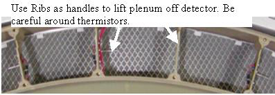
- If the fan plate was removed, use the Ribs as handles to lift
plenum off detector. If the fan plate was left on, can use the eyebolts
to hold the plenum during removal. Be careful around thermistors.
Lift plenum straight away from the gantry to avoid bending the plenum
alignment pins on either side of plenum. (see Figure 5)
The filter assembly is attached to the rear of the plenum. The back side of the filter is an EMC screen that can be damaged if poked or hit blocking air flow. Make sure the plenum is set on a flat clean surface and not on top of any small objects that can poke the EMC screen.
Figure 5. Air Plenum
- Perform the work for which the plenum was removed.
3 Plenum Installation
Procedure
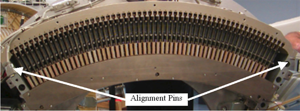
- Install the air plenum housing being careful not to hit the
EMC mesh on the backside of the plenum during installation. Plenum
alignment pins on either end of detector casting can poke holes in
the EMC mesh. (see Figure 6) Make sure no cabling is caught
between the detector casting and the air plenum.
Figure 6. Alignment pins for plenum
- Torque plenum top and side M8 screws to the value shown in Table 5.
- Torque plenum bottom M6 screws (into light seal plate) to the
value shown in Table 6.
- Install the fan plate if removed and torque the 12 screws to Table 7.
- Reconnect fan control lines and all plenum cabling. Remember the connections on the rear of the older Fan Control and Heater Control assemblies. Install ty-wraps for any removed.
- Reinstall the cable safety covers over the CFC and DHC, for
2006 style plenum, and torque screws to:
- Continue with the procedure that required plenum removal/installation.
4 Finalization
Procedure
- When power is restored to the gantry, check to make sure all 5 plenum fans are running. Use a piece of paper or similar object to make sure fans are pulling air into the plenum. A fan that is not running will still have the fan blades moving as air is pushed back out of the plenum through that fan port.
- Perform finalization steps appropriate for the task that required removing the detector plenum.