
- Discovery MR750w and SIGNA™ Architect T 3.0T System Service Methods
- 5690002-2EN Revision 4
- 00000018WIA3026D630GYZ
- id_196331472.15
- Oct 11, 2021 8:57:27 PM
Applying LOTO - RF subsystem (magnet room electronics)
Prerequisites
| Personnel requirements | |||
|---|---|---|---|
| Required persons | Preliminary requirements | Procedure | Finalization |
| 1 | - | 30 minutes | - |
| Tools and test equipment | |||
|---|---|---|---|
| Item | Quantity | Part number | Manufacturer |
| RED Logout Tagout Lock with Each Lock Uniquely Keyed | 1 | 5451778 | - |
| Multi-Locking Device (if multiple service personnel are involved) | 1 | 46-194427P313 | - |
| Red Warning LOTO Tag | 1 | 46-194427P322 | - |
| Digital Voltmeter (DVM) | 1 | 46-194427P284 | - |
| Safety |
|---|
|
Before working in any GE Healthcare MR suite or performing any GE Healthcare service procedure, you must:
If you have any safety concerns at any time, do not begin work or immediately stop work and move to a safe location. Immediately contact your supervisor or site safety officer for instructions on how to proceed. |
| Warning | |
|---|---|
About this task
- There are two types of PDUs/PGR Cabinets. The LOTO steps are the same, but the physical components are slightly different.
- This procedure does not cover the Gradient Filter. For LOTO requirements of the Gradient Filter, refer to LOTO for the PGR PDU/Gradient Subsystem.
| Affected by LOTO | ||||
|---|---|---|---|---|
| Name of equipment | Number of locks | Titles of employees authorized to perform LOTO | Titles of affected employees | How to notify |
Examples of RF Subsystem components
Examples of Pen Cabinet Electronics
Examples of Magnet Room Electronics
| 1 per GE Field Engineer (FE) | GE Field Engineers | Hospital Personnel | Verbal, Posted signs |
| Energy source | Yes | No | Location of energy | Magnitude/type of energy |
|---|---|---|---|---|
| Electrical | x | Power, Gradient, RF Cabinet (PGR) PDU (power distribution unit) Circuit Breaker Panel | 208 VAC | |
| Pneumatic | x | |||
| Hydraulic | x | |||
| Gas/Water/Steam | x | |||
| Chemical | x | |||
| Mechanical Motion | x | |||
| Gravity | x | |||
| Springs | x | |||
| Thermal | x | |||
| Stored Energy | x | Time discharge of internal capacitors | 170 VDC | |
| Air Under Pressure | x | |||
| Oil Under Pressure | x | |||
| Water Under Pressure | x | Heat Exchanger Cabinet (HEC) PGR Pump Circuit Breaker (PPMPCB) and RF amp quick disconnect | 5.0 Bar (80 psi) | |
| Gas Under Pressure | x | |||
| Steam | x | |||
| Other | x |
Procedure
- Turn the circuit breaker at the bottom of the RF amplifier to the OFF position.
Figure 1. MR750w RF amplifier circuit breaker 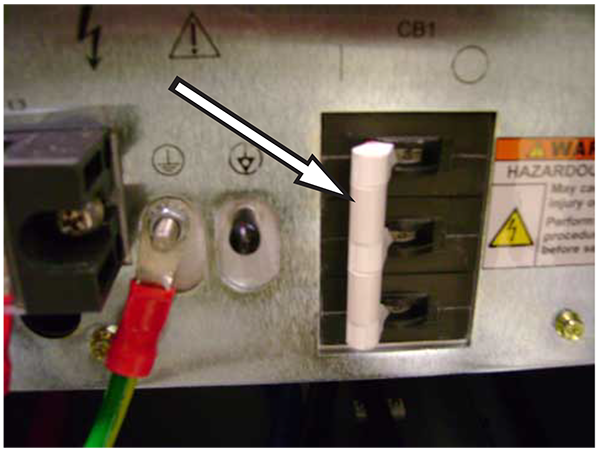
- At the front panel of the PDU, switch the PDM-RF (or RF+MNS) circuit breaker to the OFF (down) position.
Figure 2. Old style RF amp circuit breaker 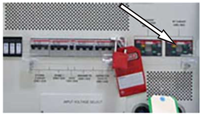
Figure 3. New style RF amp circuit breaker 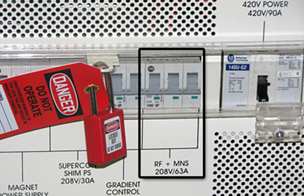
- Make sure the power is OFF. Look at the RF Amplifier LEDs to see that all LEDs are dark to visually confirm that the power is OFF. The following illustration shows an typical RF Amplifier with the LEDs still lit.
Figure 4. LED example 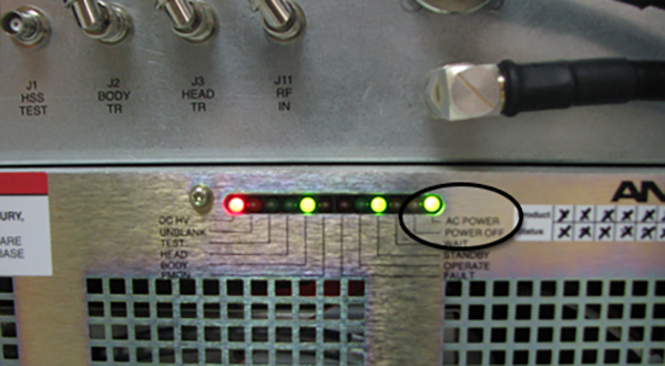
You can verify that all energy has been dissipated by measuring 0 VAC at the terminal block, as described below.
Note: It may take several minutes for lights to completely turn off.If the LEDs are on, confirm the PDM-RF (or RF+MNS) circuit breaker is in the OFF position.
- Measure voltage across the terminal block where the RF Amp receives power.
- Confirm 0 volts before proceeding.
Figure 5. Terminal block (MR750w) 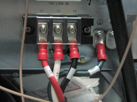
- Confirm 0 volts before proceeding.