XFD Power Panel Assy
Prerequisites
Procedure
- Remove SC Front. Refer to SC Cover Removal
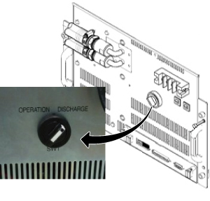
- Turn the SW1 to Discharge on front of XFD-PS.
Figure 1. Discharge
 caution
- Wait for 30 minutes.
- Go to Magnet Room.
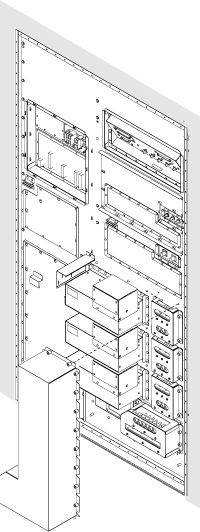
- Remove Cover for XFD Power Pannel Assy.
Figure 2. Cover for XFD Power Pannel Assy.
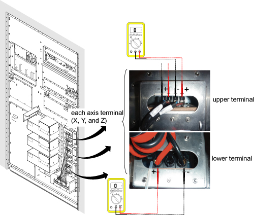
- Check the voltage at each axis terminals (X, Y, Z) and confirm
that there is no voltage. Refer to Figure 3 for voltage
check point.note:
Normally, the voltage of upper terminal will be 0 V after 30 minutes.
For lower terminal, the voltage may exist in case of switch failure in XFD-PS and the charge of super capacitor cannot be discharged.
If voltage exists in lower terminal, please check that SW1 of XFD-PS is turned to discharge position.
If SW1 is at discharge position, waited for 30 minutes, and voltage still exists at lower terminal, consider to replace XFD-PS before replacing XFD Power Panel Assy.
Figure 3. Voltage Check
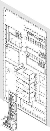
- Remove defective XFD Power Pannel Assy.
Figure 4. Cabinet Interface Board Cables
- Bring new XFD Power Pannel Assy and connect all the connectors to three XFAs and XFD-PS.
- Tighten all screws XFD Power Pannel Assy.note:
Make sure to tighten each screw.
- Restore Cover for XFD Power Pannel Assy.note:
To install cover, start screwing from the corner. Do not tighten until all screws are screwed in the screw holes. Finally tighten all screws.
- Turn the SW1 to OPERATION on front of XFD-PS.
- Restore Cabinet cover.
1 Finalization
Procedure
- Restore the Power. Refer to Lockout / Tagout for MDP(Main Disconnect Panel) or Facility PDU.
- Perform Signal to Noise - Head Scan.