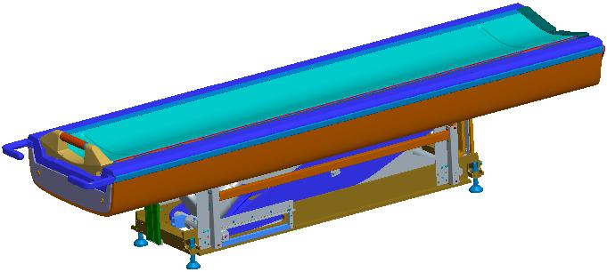
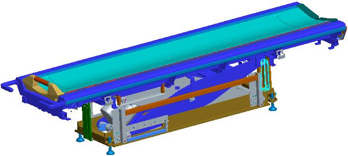
Tabletop assy, LH TBL
Prerequisites
Procedure
- Turn the system power OFF
- Disconnect the Table from MR Magnet and ground; take it out from the Magnet room.
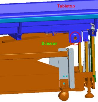
- Remove the scissor covers from the table.
Figure 1. Remove the scissor covers from the table.
- Remove the Cradle from the Table.
Figure 2. Remove the Cradle from the Table
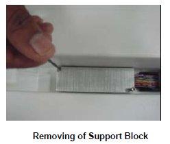
- Remove the Support block fixed to the tabletop for the cables.
Figure 3. Remove the Support block fixed to the tabletop for the cables
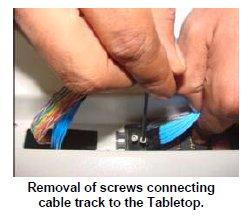
- Remove the Cable tract connecting screw to the table top.
Figure 4. Remove the Cable tract connecting screw to the table top
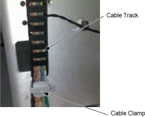
- Remove the cable strap, cramp and track and remove cables.
Figure 5. Remove the cable strap, cramp and track and remove cables
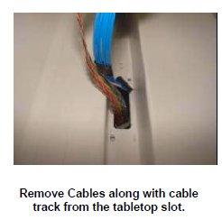
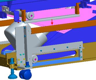
- Remove the Cable assemblies along with the cable tract from
the Tabletop.
Figure 6. Remove the Cable assemblies along with the cable tract from the Tabletop
- Remove the Table Top side FRP covers fixing screws in the Table
and remove side FRP coversside FRP covers
Figure 7. Remove the Table Top side FRP covers fixing screws in the Table and remove side FRP coversside FRP covers
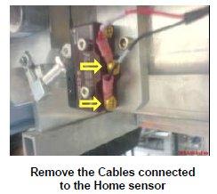
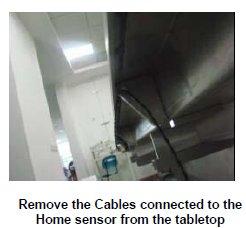
- Remove the cables connected to the Limit switch of the home
sensor.
Figure 8. Remove the cables connected to the Limit switch of the home sensor
- Remove the Home sensor Cable assembly from the Tabletop.
Figure 9. Remove the Home sensor Cable assembly from the Tabletop
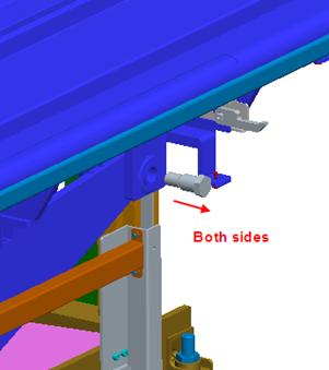
- Remove wheel guide fixing screws and then remove wheel guides
Figure 10. Remove wheel guide fixing screws and then remove wheel guides
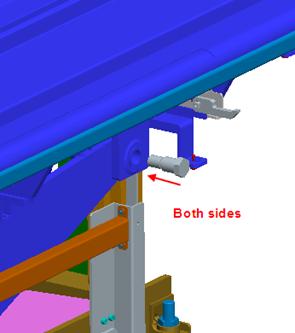
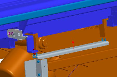
- remove 2 shafts connecting tabletop and table scissor
Figure 11. Remove 2 shafts connecting tabletop and table scissor
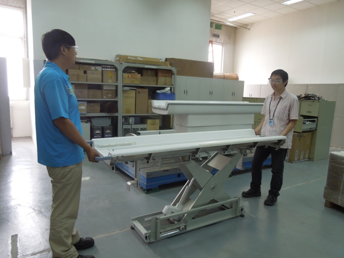
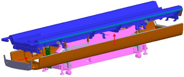
- Now the Table top is free in the Table. Lift the Table Top from
the base/scissor assembly.
Figure 12. Lift the Table Top from the base/scissor assembly

- Put down the New Table top on base/scissor assembly.
Figure 13. Put down the New Table top on base/scissor assembly
- Move the Table top on either side and adjust such a way that
the 2 shaft holes of table top will align with the scissor hole.
Figure 14. Move the Table top on either side and adjust such a way that the 2 shaft holes of table top will align with the scissor hole
- Install the 2 shafts connecting tabletop and table scissor
Figure 15. Install the 2 shafts connecting tabletop and table scissor
- Install wheel guides
Figure 16. Install wheel guides
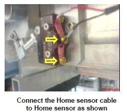
- Install the Home sensor cable in the table top.
- Connect the Home sensor cable to the Home sensor.
Figure 17. Connect the Home sensor cable to the Home sensor
- Install tabletop side FRP covers.
Figure 18. Install tabletop side FRP covers
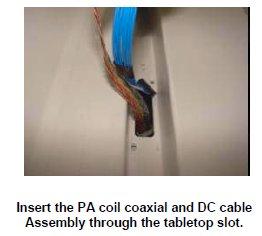
- Insert the PA coil coaxial and DC cable Assembly from the top
of the Tabletop.
Figure 19. Insert the PA coil coaxial and DC cable Assembly from the top of the Tabletop
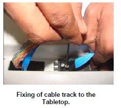
- Fix the Cable track of the PA coil coaxial and DC cable Assembly
to the Tabletop.
Figure 20. Fix the Cable track of the PA coil coaxial and DC cable Assembly to the Tabletop
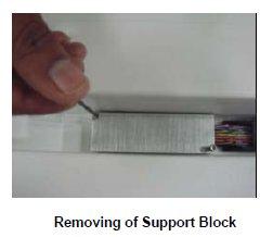
- Fix the support block to the Table top.
Figure 21. Fix the support block to the Table top
- Rout the cables in the table and wind the spiral tube around
all Assemblies.
Figure 22. Rout the cables in the table and wind the spiral tube around all Assemblies

- Assemble the cradle to the table.
- push the table back to magnet room and connect it with Dock frame
- Connect the cables of the table.
- Level the table.
- Dock centering and Height adjustments.
- Fix the scissor covers from the table.
- Fix the FRP Base Covers of the Table.
Finalization
- Turn the system power ON. Refer to Lockout / Tagout for System Cabinet PDU Main Breaker.
- Level the Table and perform Height Adjustment. Refer to LEVELING FIXED TABLE and TOP HEIGHT ADJUSTMENT.
- Fix the FRP Covers of the Table.
- Perform CRADLE HOME SENSOR CHECK .
- Check the Table Function. Refer to TABLE CHECKS AFTER INSTALLATION .
- Perform Express Coil MCQA Test to check that the PA coil cable is properly connected.