Remove the scissor covers from the table. SCISSOR COVERS
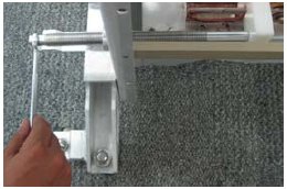
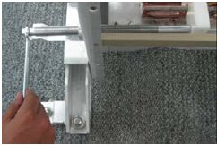
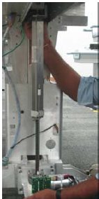
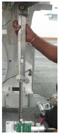
Assemble lock screw rod to lock position of scissor.
Figure 2. Assemble lock screw rod
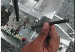
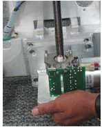
Remove 4 screws of actuator mounting bracket.
Figure 3. 4 screws
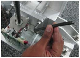
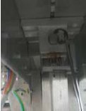
Remove circlips & pin. Remove actuator.
Figure 4. Remove circlips & pin
Figure 5. Remove actuator
note:
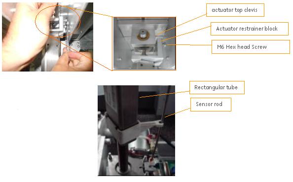
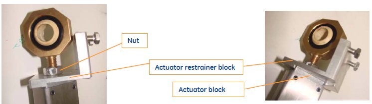
Before assembling new Actuator assembly, Ensure Actuator
restrainer bracket is position to actuator block as shown. also ensure
Nut to flush above Actuator restrainer bracket, do not tighten.
Figure 6.
Assemble pin & circlip for new actuator. In this case, actuator
mounting bracket holes will not be aligned with tapped hole in lower
base of table.
Figure 7. Assemble pin & circlip for new actuator
Figure 8. Placing Actuator
warning
FE DO NOT replace actuator FRU kit by screw rode to lift
the table during install. This type actuator is designed to support
push force only, it is dangerous to use the screw rod to raise the
table manually when the actuator is still connected.
notice
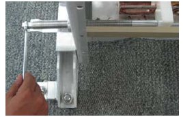
FE can't Rotate lock screw rod to move tabletop up.
Rotate lock screw rod to move tabletop down and align screw
mounting holes.
Figure 9. Rotate lock screw rod to move tabletop down
Assemble actuator mounting screws and tighten.
Figure 10. Assemble actuator mounting screws
Remove lock screw rod.
Figure 11. Remove lock screw rod.
Arrest the restrainer block play by tightening the M6 hex head
screw
Tighten 2 screws till it butts against actuator top clevis,
with this the Gap/play will be arrested between Actuator restrainer
block and actuator top clevis.
Above mentioned adjustment are made to ensure sensor rod is
both vertical & parallel to rectangular tube during actuator
up down motion & arrest sensor rod tilting.
Figure 12. Tightening the M6 hex head screw
Take the table to Magnet and restore the table. Refer installation
manual for the Table installation procedure.
 warning