Rear End Bell Removal
Prerequisites
Procedure
- Remove following assembly and covers.
-
Bridge assembly (Refer to Bridge Assembly.)
-
Rear pedestal (Refer to Rear Pedestal Removal.)
-
Rear trim ring (Refer to Rear Trim Ring.)
-
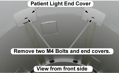
- Remove the patient light end covers from the upper side of magnet
bore by removing 2 bolts.
Figure 1. Patient Light End Cover Removal
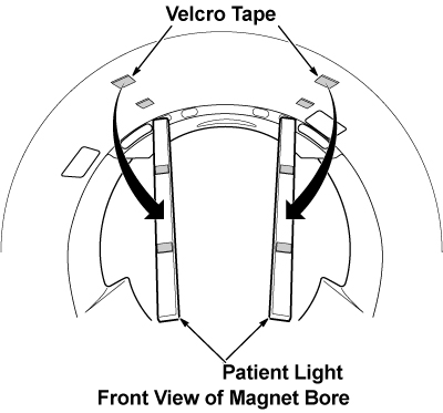
- Remove the patient lights from the magnet bore upper side. The
patient light is secured by Velcro tape.
Figure 2.
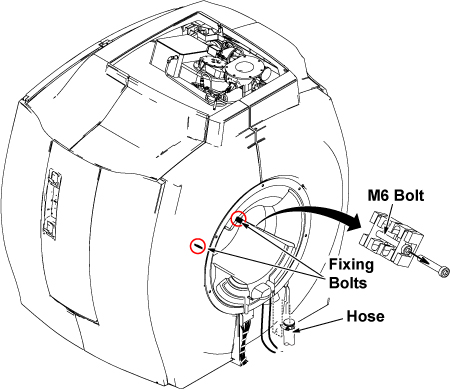
- Loosen the clamp screw, and remove hoses. (Refer to illustration 3)
- Using an M5 Allen wrench, remove the two M6 bolts of fasteners
which connect the RF coil and the rear end bell. (Refer to illustration
3)
Figure 3. Hose and Fixing Bolts Removal
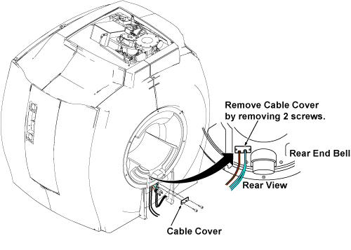
- Remove the cable cover from the rear end bell by removing 2
screws.
Figure 4.
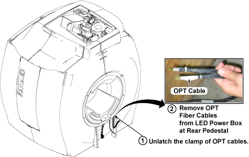
- Unlatch the clamp of OPT cables. (Refer to illustration 5.)
- Disconnect the OPT fiber cables from LED Power Box assembly.
(Refer to illustration 5.)
Figure 5. Disconnect OPT Cables
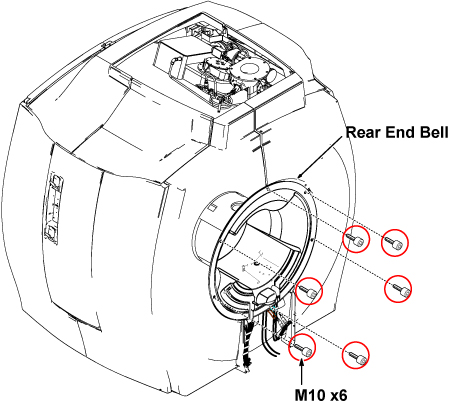
- Remove the 6 bolts (M10 x6) securing rear end bell to the magnet.note:
Do not remove the rear end bell. The rear end bell is connected by speaker cable.
Figure 6. 6 Bolts Removal of Rear End Bell
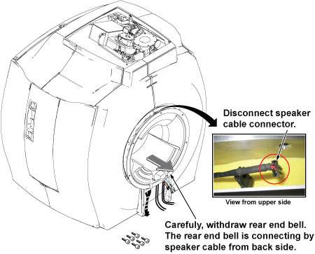
- Withdraw rear end bell until can access to speaker cable connector.
- Disconnect the speaker cable from the magnet upper side.
Figure 7. Disconnect Speaker Cable
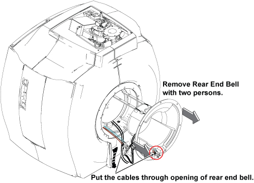
- Remove the rear end bell from the magnet bore.
Figure 8. Rear End Bell Removal
- Installation is reverse order of removal.
Finalization
No finalization steps.