RF Shield Replacement
Prerequisites
Procedure
- Move Carriage Assembly all the way back to rear of bridge.
- Turn off Power to Gradients and RF Cabinet. Lock and Tag out PDU Breakers.
- Remove End-Bell Covers, both Front and Rear to gain access to RF Body Coil.
- Remove RF Body Coil (Refer to Replacing BRM RF Body Coil .).
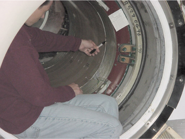
- Mark current placement of RF Shield. Reference Figure 1 while performing steps Step 5.a – Step 5.c.
- Using the Black Sharpie Pen, mark the position of the current
front position of the RF Shield in the Z-Axis at the point where the
copper starts. This is best done near the 6 o’clock (bottom)
position of the RF Shield. Also verify the radial position is marked
at the 180 or 90 degree position (Bottom Dead Center for both). There
should be a black mark on both the Gradient Coil and RF Shield indicating
the 180 or 90 degree placement of the shield. If not, make a small
mark on the Gradient coil. Figure 1.
Figure 1. Mark current placement of RF Shield
- It’s usually a good idea to mark both sides. Repeat previous step on rear side of RF Shield.
- Note the orientation of the 8 or 9 individual fiberglass straps that hold the RF Shield securely against the inner Gradient Coil surface. Once the new RF Shield is installed the new straps should be reinstalled in the same order and roughly in the same location and in the same pattern (TRM straps alternate in orientation).
- Using the Black Sharpie Pen, mark the position of the current
front position of the RF Shield in the Z-Axis at the point where the
copper starts. This is best done near the 6 o’clock (bottom)
position of the RF Shield. Also verify the radial position is marked
at the 180 or 90 degree position (Bottom Dead Center for both). There
should be a black mark on both the Gradient Coil and RF Shield indicating
the 180 or 90 degree placement of the shield. If not, make a small
mark on the Gradient coil. Figure 1.
- Removal of Fiberglass straps.
 warning
- caution
- Using non-magnetic spatula supplied in tool kit, remove the plastic cover to expose the sharp end of the spatula.
- At the 6 o’clock position of the RF Shield and away from the ends of the fiberglass straps, carefully slide no more than 0.5 inches (1.27cm) of the sharpened tip of the spatula between the fiberglass strap and top copper trace of the RF Shield. Avoiding working directly over one of the two solder seams that run the length of the RF Shield. These are easy to see through the fiberglass straps.
- Place the plastic Wedge from the tool kit underneath the Spatula
and push the Wedge forward to lift the fiberglass strap so that the
end of the Wedge adjoin against the neighboring strap. This will
cause a “bubble” in the strap. See Figure 2.
Figure 2. Working Strap Up
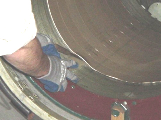
- Place your gloved hand over the end (seam) of the strap and then move the wedge and “bubble” around to the fiberglass strap end and, using 2 hands, carefully “open” the 2 ends apart. Hold the strap ends while removing the strap from the gradient coil as there is a tendency for the straps to relieve their tension and snap back into place.
- When preparing to remove the remaining straps, it’s best to pick an area on the RF Shield where there is a wide copper trace so that the Spatula doesn’t cut into the material between the traces on the RF Shield. Again, don’t start at the end of the strap.
- After the first strap is removed, repeat the above steps to
remove all the remaining straps. The number of straps to remove will
vary depending on Gradient Coil type (ie. BRM, CRM, TRM, 3T). Figure 3.
Figure 3. Straps


- Replace plastic cover on sharp end of Spatula and return tools to case.
- Removal of RF Shield
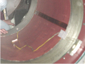
- Make sure the RF Shield ground wire (if any) is disconnected from the Magnet. Save the tape removed from the ground wire for re-use later.
- Carefully remove any tape holding the ends of the RF Shield to the Gradient Coil.
- After ALL the straps have been removed, take the supplied flat aluminum ruler and slide it between the RF Shield and Gradient coil from front to rear on the top of the shield until there is an equal amount of ruler extending out from each end of the RF Shield.
- Using 2 people, one person in front and one person in the rear,
twist the meter stick 90 degrees and pull down so the middle of the
RF Shield gently collapses, to the bottom of the Gradient Coil without
any sharp bends or creases. Figure 4.
Figure 4. Collapsed RF Shield
- One person then places their arms through the RF Shield and
removes the shield as shown in Figure 5.
Figure 5. RF Shield
- Measure the length of the ground wire from the old shield and compare it with the length on the replacement shield. On early magnets (S3), you will need to splice, solder, and tape an extension ground wire since the RF Shield already has a ground strap installed and cut to length for a LCC Magnet. Make sure you have a good solder connection, no loose ends and no cold solder joint.
- notice
- Clean the inside of the Gradient Coil using a clean lint-free
rag and, if available, a small amount of isopropyl alcohol. No loose
solder material, debris, or other contaminants should be left inside
the Gradient Coil.
Figure 6. Cleaning Bore
- Open the RF Shield FRU container to expose the replacement RF Shield affixed to the cardboard tube.
- notice
- Carefully remove the pieces of tape affixing the front and rear of the replacement RF Shield to the cardboard tube. Save the pieces of tape for later reuse.
- notice
- Wipe down the outside of the RF Shield with a lint-free cloth so that it is free of surface debris.
- Remove the supplied aluminum ruler from the FRU container and lay it on top of the RF Shield so that it is parallel with the length of the RF Shield. The ruler ends should extend out equal distances from each end of the RF Shield.
- Securely affix the ruler to the RF Shield using the pieces of tape that were removed earlier.
- Slide the RF Shield and ruler assembly forward so that it extends about 6 inches (15.2cm) over the front edge of the cardboard tube.
- Locate the black scribe marks (one of them may be labeled “90” or “180”) and the word “FRONT” hand-printed on the inside, front of the RF Shield. If you instead see the word “REAR” then you will need to remove the cardboard tube and shield assembly from the FRU box, move the front end around 180 degrees to the rear end, and reinstall it into the FRU box so that the part of the RF Shield marked “REAR” is indeed now located at the rear of the FRU box. The ruler will also need to be re-positioned at this time.
- Rotate the cardboard tube on the extended FRU box arm so that the portion of the RF Shield with the scribe marks is located at the 6 o’clock (bottom-most) position.
- notice
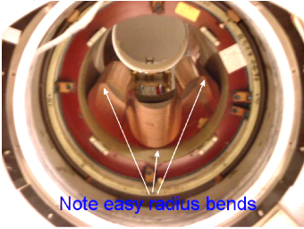
- The RF Shield must be removed so that the center of the shield is bowed in on itself with a wide bend radius at all bend points. It can only be installed into the Gradient Coil in this shape. The purpose of the affixing the aluminum ruler along the length of the top of the RF Shield is so that the extra weight added by the ruler can make this bowing-in action happen when one person is removing the shield from the FRU box tube fixture. If two people are available then using the ruler in this manner may not be necessary. The other person can help make sure that the bowing action occurs as the RF Shield is removed from the cardboard tube.
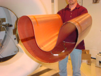
- Carefully pull RF Shield off of the cardboard tube and support
it from the inside using both arms as shown in the illustration below.
The top of shield will bow inward with a wide bend radius at the
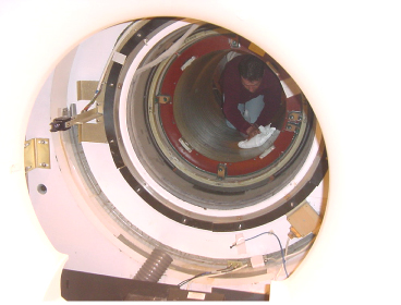
specified points as shown in the Figure 7. Carry the RF Shield to the front of the Gradient Coil and place
it inside as shown in the Figure 8. Leave it in the “bowed”
position inside the Gradient Coil.
Figure 7. Carefully Handle Shield
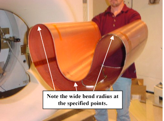
Figure 8. Shield in Bowed Position Inside Gradient Coil
- Confirm again that the part of the RF Shield hand-marked “FRONT” is indeed at the front of the Gradient Coil.
- If the ruler was affixed to the RF Shield then carefully remove it and the tape from the RF Shield and from the Gradient Coil.
- With the RF Shield still in the “bowed” position, align the 180 or 90 degree marks on the RF Shield as closely as possible with those marked on the bottom of the Gradient Coil. The new RF Shield needs to be installed in the same position and orientation as the old RF Shield.
- Align the RF Shield from front to back so that it aligns with the front and rear Z-direction scribe marks made earlier on the Gradient Coil before the old RF Shield was removed.
- Taking care to not expose any part of the RF Shield to a tight bend radius that would result in creasing of the RF Shield, carefully push “bowed” portion of the RF Shield up, while taking care to maintain it’s position inside the Gradient Coil, until the RF Shield contacts against the surface of the Gradient Coil. Once installed, the RF Shield should lie completely flat against the Gradient Coil inner surface and should be aligned as close as reasonably possible to the Gradient Coil scribe marks.
- If you find that you need to move the RF Shield again for re-positioning
you can use the ruler to “bow” it as you did when removing
the old RF Shield. Before using the ruler to do this, however, make
sure that the ruler ends are free of burrs and that the ruler ends
won’t scratch the surface of the new RF Shield during insertion.
This may require some light filing. Try to limit yourself to repositioning
the RF Shield in this manner to no more than one time after installation.
- warning

- notice
- Install the supplied RF Shield retaining straps.
- Discard the old fiberglass straps and use the new fiberglass straps supplied in the FRU container. If it is necessary to use an old strap then it may be necessary to remove a small amount of fiberglass material from one end of the strap. See the Note at the end of this document.
- Clean and install 1 strap at a time. Usually it is best to start from the front and work to the back. The position of the first strap is the most critical, since each strap must be aligned and each abuts edge to edge against the other. If the first strap is mis-aligned then all other straps will also be out of alignment.
- The orientation of the straps depends on the Gradient Coil type. The first strap inside a TRM must be aligned so that the end is located either at the 3 o’clock or 9 o’clock positions. The end of the second strap starts at the opposite location of its neighbor (either 3 or 9 o’clock) and abuts directly against its neighbor and interlocks with a special notch on the neighboring strap. This pattern continues until all 8 of the TRM fiberglass straps are installed.
- The first strap inside a BRM or CRM must be aligned so that
the end is located either at the 5 o’clock or 7 o’clock
positions. The end of the second strap starts at the opposite location
(either 5 or 7 o’clock) of its neighbor. Each strap abuts directly
against its neighbor but these straps don’t have notches. This
pattern continues until all of the remaining fiberglass straps (8
for CRM and 9 for BRM) are installed.
-
The best way to install a fiberglass strap is to bend the strap in a circle so the ends are overlapped, then place inside the RF shield.
- warning
Rotate the strap so the end is in the proper location for the coil type. See previous discussion.
-
Create a “bubble” near the center of the strap and then abut the ends of the strap together. Be careful not to let the strap ends “DIG” into the bare mylar or copper trace. Verify proper positioning.
- notice
Position the edge of the strap so that it aligns with the edge of the copper trace on the RF Shield. It should completely cover the copper portion of the end of the RF Shield but should not overlap much into the non-copper portion of the RF Shield. Verify alignment all the way around the strap.
-
After verifying strap position and orientation, use the heel of one or both of your gloved hands to press on the “bubble” until it “snaps” in place. This usually takes much force, after which a loud snap is heard. Take care not to catch your fingers or rubber gloves under the strap.
 note: Pressing the “bubble” into place is usually easy to do on pre-existing straps. It may not be possible to do this for new straps. The ends of new straps that will not “snap” into place can be lightly filed. Do not over-file the ends of new straps as all the copper portions of the RF Shield must be held firmly in place against the gradient coil inner surface and must not, under any circumstances, move during scanning.
 -
- Install all the other straps, alternating end positions so that the straps lay flush against each other, so that there are no gaps and so that the straps do NOT overlap.
- Reconnect the ground wire from the RF Shield to the magnet face or foot. Secure the wire in place with tie-wrap and salvaged tape.
- On the Service end of the Gradient, apply a strip of Kapton Tape 46-208785P2) to secure the exposed edge of the RF shield Teflon Spacer. Apply tape starting at 270o point over the entire circumference. Half of the tape should be applied to BRM ID FRP and half to the edge of the RF shield Teflon spacers. The tape is used to eliminate noise cause by gradient blower air moving through the Teflon Spacers.
|
|
|
|
1 Finalization
Procedure
- Reassemble the magnet subsystem.
- Run Grafidy.
- Run Echo Planar Test.
- Run Probe/SV Calibration and SNR Tests if applicable.