Replacing BRM RF Body Coil
Prerequisites
The RF body coil cartridge is a FRU that mounts inside the gradient coil (also a FRU), and is available in 1.0T and 1.5T versions. If the RF coil fails, it must be removed from the gradient coil and replaced with a new one. Since the replacement procedures for the RF and gradient coils are closely related, references are made below to the epoxy-filled gradient coil replacement procedure where the instructions for removal of like parts (for example, bridge removal) can be found. Although some tasks (such as connecting/disconnecting various cables, etc.) can be accomplished by one person, replacing a failed RF body coil requires three people.
1 Unpacking BRM RF Body Coil
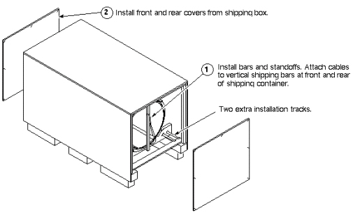
A new RF body coil is packed in a cylindrical shipping container that is strapped inside a combination pallet and outer shipping box. It rests on a pair of installation tracks. The shipping container never leaves the box; the RF body coil is removed from this combination. Included are two extra installation tracks used in the gradient body coil to assist in the RF coil exchange.
Procedure
 caution
- caution
- To perform all necessary steps for this part of the procedure,
refer to each of the illustrations that follow.
Figure 1. Unpacking New BRM RF Body Coil
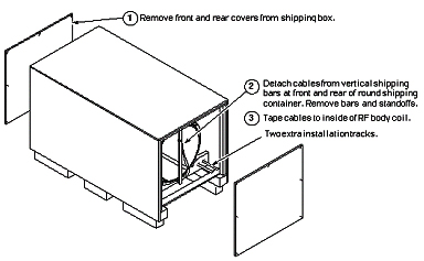
Figure 2. Separating BRM RF Body Coil from Shipping Container
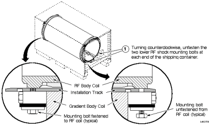
Figure 3. Shifting Installation Tracks in BRM Shipping Container
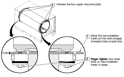
Figure 4. Removing BRM RF Body Coil from Shipping Container
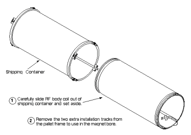
Figure 5. Placing Extra Installation Tracks Under BRM RF Coil
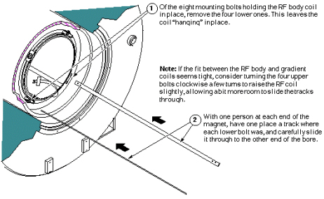
Figure 6. Attaching Tracks to Gradient Body Coil
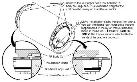
Figure 7. Sliding Out RF Body Coil onto Tracks
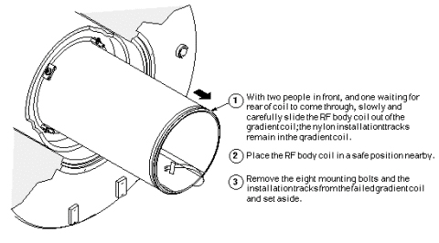
Figure 8. Sliding New RF Coil into Place
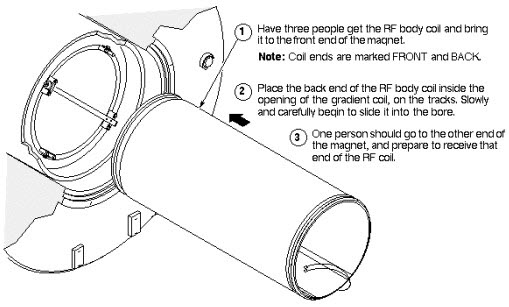
Figure 9. RF Coil Attachment and Track Removal
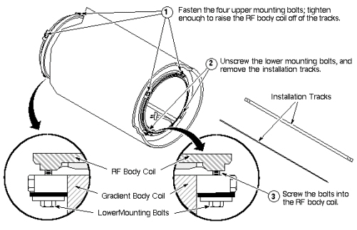
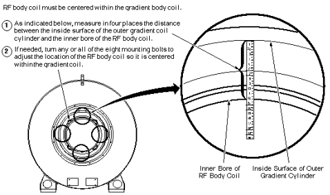
Figure 10. Centering BRM RF Coil in Gradient Coil
- Complete the remaining installation steps per New Gradient Coil Installation.
 |
|
2 Preparing Failed BRM RF Body Coil for Shipment
Procedure
- Refer to the illustrations below for instructions on packing
the failed BRM RF body coil for shipment.
Figure 11. Loading Failed RF Coil into Shipping Container
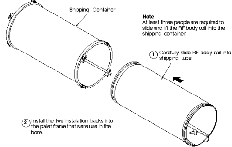
Figure 12. Fastening Installation Tracks to Shipping Container
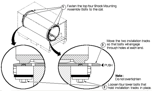
Figure 13. Securing BRM RF Coil in Shipping Container
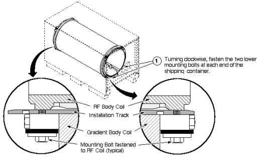
Figure 14. Closing BRM RF Shipping Container and Box
- Ensure shipping container is ready for shipment.
3 Finalization
Procedure
- Clean up the site in preparation for patient scans.
- Run head and body test scans to ensure proper operation.