Probe-P Calibration and SNR Tests
Prerequisites
1 Overview
This material applies to the system with probe-p option and describes hydrogen ONLY spectroscopy (Probe/SV) procedures:
-
Echo Peak Location Calibration (automated Probe Tuning script) for BRM ONLY
-
Probe SNR performance test
The Tuning procedure determines the values of control variables (CVs) that are necessary for Probe/SV scanning. Each Tuning scan will result in 18 coordinate values (three sets of six). Within each set of six, the first four values are described as A, C, B, and D. The 5th is E or - Verification, and the 6th is F or + Verification. Additional calculations (using the first four values of each set) are performed, and the resulting values will be automatically entered into a calibration file producing site specific Control Variables. The SNR procedure will be performed after the Tuning procedure.
note:Software will not correct specific sites effected with tuning anomalies. Sites with APS failures due to Water Suppression during SNR should use the appropriate type-in PSD (Probe-p2). If necessary, call the OLC for assistance. Depending on the failure, a PQR may be required.
2 Probe-P Tuning Procedure (Echo Peak Location Calibration)
Procedure
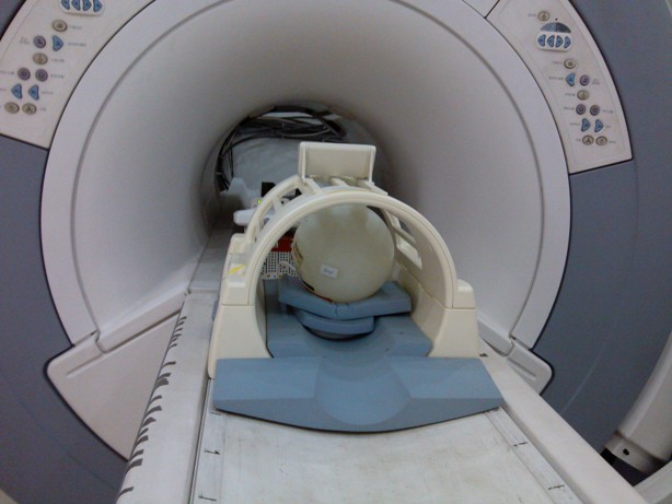
- Position the phantom on the head support in the head coil with
the temperature strip visible. Do not use the tuning ring or head
loader with the MRS phantom. Use foam padding as necessary to center
the phantom in the head coil. Phantom-centering (up/down/left/right/in/out)
within 5mm of ISOcenter in all directions is important. See Figure 1. Run any head
localizer to ensure the phantom is properly centered before beginning
the Probe tuning procedure. Landmark on DQA-Landmark.
Figure 1. Position of the Phantom
- Follow the steps below for Probe/P Tuning.
Do not use the geservice protocol probepcal. This is the alternate proprietary procedure available for GE use, and to sites with a valid Advanced Service Package Limited License.
- Start the Probe/P Tune Tool.
-
Restricted Service tools available to GE Field Service. Make sure your service key is installed. Select Calibration Wizard from the calibration menu and select Click here to start this tool. Once the Calibration Wizard starts, select Probe/P Tune from the menu, review and okay the pre & post-dependencies, and select Click here to start this tool to start the procedure. If you are unable to start the Restricted Service tools, use the non-proprietary method described in the next bullet.
-
Starting non-proprietary service tools: From the Common Service Desktop, select Calibration, Probe/P Tune from the calibration menu, and select Click here to start this tool to start the procedure.
-
- Refer to Data Sheet for the Tuning Data Sheet.
- The Probe /P Tuning Window pops up, with a comment reminding
the user to landmark on the table as geservice. Hit [Enter] to acknowledge,
and the calibration will begin as shown below:
Probe-P Cal Started
xshim=# yshim=# zshim=#
APS: R1=## R2=## TG=### CF=########
The tuning process will proceed automatically for each axis:
delta#_val: #.##
# AXIS Calibration completed Successfully
A message will appear after completion of the 3 axis:
Probe/P Tuning completed successfully.
Results are stored in the /usr/g/caldir/probes_cal.log
If Probe-P cal does not complete successfully: rescan, if still failing re-run grafidy.
Press [Enter] to quit
- To view the complete results (which do not contain APS information):
- Select C Shell....
- Type: more /usr/g/caldir/probep_cal.log
- The specification criteria (absolute value) are:
-
Single delta parameter, I < .8 I
-
Sum of all delta parameters, I < 1.0 I
-
3 Probe-P SNR Procedure
Procedure
- Set up the Service scan prescription by following the instructions
below. This is the alternate proprietary procedure available for GE
use, and to sites with a valid Advanced Service Package Limited License.
For Non-Service protocol refer to Manual Entry Probe/SV SNR Protocols.note:
The MRS Phantom must be used for all SNR procedures. Position the MRS phantom on the head support in the head coil with the temperature strip visible. Do not use the tuning ring or head loader. Use foam padding as necessary to center the phantom in head coil. Phantom-centering (up/down/left/right/in/out) within 5mm of ISOcenter in all directions is important. Run any head localizer to ensure that the phantom is properly centered before beginning the PROBE SNR procedure.
This is the alternate proprietary procedure available for GE use, and to sites with a valid Advanced Service Package Limited License.
- If whole mode, select Whole, then OK, or
If zoom mode, select Zoom, then OK.
- Save Series.
- Select Research Operations using the mouse, then right-click.
-
Display CVs. Highlight the CV Name and
enter the following:
- Accept.
- Research Operations Download.
- Scan (the system will Auto Prescan then Scan).
- Select Message Window, which is located in upper left-hand corner of the scan desktop. Record R1, R2, TG, AX, (if present, record FWHM, WS Angle, WS%) on the Data Sheets. Close the window.
- SNR is not annotated on the auto viewer; you must access the image from the Browser on the Display (Advantage Windows) Desktop. On this desktop, click on Browser, Sort, Sort examinations by date. Once you have done this, the most current exams will be displayed in the upper window. Select the most current Image from the most current Series from the lower window, and click on Viewer. Select Format, then click on the single box (in the upper left corner).
- Record the displayed results on the Data Sheets for Probe-P SNR.
- Retain a hard copy of the Probe SNR image for reference. This
can be used to make a comparison of the Cr SNR from the most recent
Probe-S and Probe-P scans with the Cr SNR previous/future scans.note:
It is imperative that a minimum of three scans be performed (back-to-back) to get an estimated average Probe-P SNR.
- Repeat Step 7 - Step 11 three times, to get an average Probe-P SNR.
- Probe-P SNR specification is:
-
(For 1.5T) 60.00 minimum
-
The MRS Phantom (without the loader) must be used for the SNR procedure. The greenest value of temperature strip must be entered as a Control Variable (tempC).
4 Help
This section contains Illustrations of Probe SNR Spectra, both incorrectly tuned and correctly tuned to familiarize the user with what a good spectrum looks like. During tuning or SNR troubleshooting, it may be necessary for a site to back up the original echoloc.dat file. This backup process requires renaming the file, otherwise, it will be overwritten during the tuning calibration. Additional information can be obtained concerning the cause of an AWS (Auto-Water Suppression) failure by logging the messages generated during the Probe APS. A site may be required to send Probe SNR raw data to an expert for review. This section explains the P raw file location process and how to transfer it.
4.1 Example SNR Spectra
Errors in the Probe Tuning Calibration Procedure can introduce changes in the appearance of the resulting Probe SNR spectra. This section contains example spectra from a Probe-P SNR protocol using the MRS phantom. Figure 2 shows a correctly-tuned spectra. Pay particular attention to the base (left and right) of the NAA (NA) peak; this is the largest peak located at the center of the spectrum.
Procedure
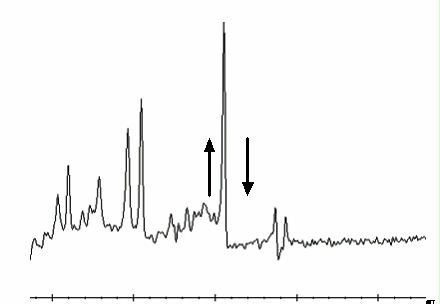
- Refer to Figure 3 and Figure 4 to view spectra with an un-calibrated tuning parameter (a delta
was offset + or - from the correct value by 0.5 units).
Figure 2. Correctly-Tuned Probe SNR Spectra
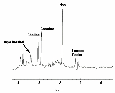
Figure 3. Incorrectly-Tuned Probe SNR Spectra
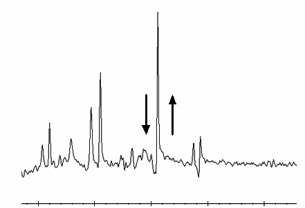
Figure 4. Incorrectly-Tuned Probe SNR Spectra
- To perform Probe Tuning File and Backup, follow these steps:
- At the MR Service Desktop, click on C-Shell....
- At the prompt, enter the following:
cd /usr/g/caldir Enter
mv echoloc.dat echoloc.bak1 Enter
- Close the C Shell...note:
The echoloc.dat file does not exist for initial software loads.
The actual file that contains the Probe Calibration values is in the caldir directory as probepfix.dat. The unlabeled values are deltax, deltay, and deltaz.
For the TwinSpeed, the file extensions .WHOLE and .ZOOM should be used and maintained when moving files.
note:Additional information can be obtained concerning the cause of an AWS (Auto-Water Suppression) failure by logging the messages generated during the Probe APS.
4.2 Directory Creation
Procedure
- On the MR Service Desktop, click on C Shell....
- Create a directory to hold the log file by entering the following:
cd /usr/g Enter
mkdir probe_data Enter
cd probe_data Enter.
- Log in to the MGD AGP and direct the output to a file and to the screen. Use the grave symbol (`) and the pipe symbol (|) on the keyboard where indicated below. Local is the lowercase “l” key.
- rlogin agp | tee agp_log Enter.
- Log in to local (l) or remote (r) vxWorks console Enter.
- Log in using the user name agp , then press Enter. When prompted, enter the password agpservice and press Enter.
At this point logging is running. DO NOT type anything in the AGP window. Watch the AGP messages appear on the screen; everything will be logged into the file entered after the tee command (tee agp_log). This file will be overwritten each time.
- Select the Rx Manager icon.
- Run Auto Prescan (APS).
- Select the Service Desktop Manager icon and use the scroll bar to review the log.
- When done, type logout in the AGP window. This will disconnect the AGP from the C Shell. A message will appear confirming logoutConnection closed.
- To view the log file created, verify that the current directory is /usr/g/probe_data.
- Type: more agp_log and press Enter.
- Close the C Shell when you’re done.
- The log file can be sent to the OLC, or e-mailed to whomever
the site is working with to resolve problems.note:
During the troubleshooting process, the site may be required to identify the P raw data files generated when Probe SNR was performed. These files may be helpful in determining a reason for SNR failure.
4.3 P Raw Data File Location
This portion of the procedure should be performed after running a Probe SNR protocol to facilitate P raw file identification.
Procedure
- At the Service Desktop Manager, click on C-Shell....
- At the prompt enter the following:
cd /usr/g/mrraw Enter
ls -lt P*| head Enter
- The most recent P files will be displayed. Record the Probe raw data file (P#####.7). The P file’s size is ~449584.
- Close the C Shell when you're done.
Finalization
No finalization steps.