GP4
Prerequisites
Procedure
- Remove L Upper Front Cover. Refer to SC Cover Removal.
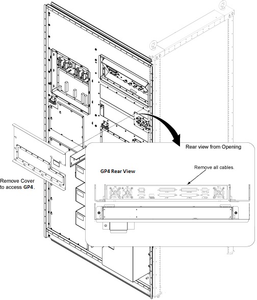
- Remove the access cover by loosening screws from SC rear panel.
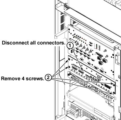
- Disconnect all connectors from rear panel of GP4. (From left
side: J7, J8, J1, J10, J11, J12 and J13 connectors)
Figure 1. GP4 Cable
- Remove 4 screws tightening GP4 to the chassis.
- Slide GP4 out from front side of the chassis.
Figure 2. GP4 Removal
- Restore GP4 by reverse order of removal.
- Restore System cabinet.
Finalization
note:
Download time can be up to 10 minutes on a replacement GP4 module. If the software loaded on the system does not match the firmware loaded on the GP4 Board received as a replacement, there will be a one-time lengthy download of current firmware to the GP4. During this download there will be a windows on host screen to remind users an extended downloading is on going. Please be patient.
- Restore the Power. Refer to System Cabinet PDU Main Breaker LOTO Procedure.
- To adjust DC Offsets, refer to DC Offset Adjustment .
- Perform [TPS Reset].
- Perform DQA Tool.