Express Coil: Posterior Array Coil Replacement without removing Fixed Table
Prerequisites
This instruction provides procedure to disassemble and assembly cradle from tabletop on the SV fixed table.
1 Cradle Disassembly Procedure:
Procedure
- System Power must be turned OFF. Refer to Lockout / Tagout for System Cabinet PDU Main Breaker .
- notice
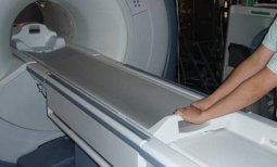
- Move the cradle inside the bore until free from the side guards (400mm - 450mm).
- Release the cradle from the LPCA.
Figure 1. Cradle Disassembly 1
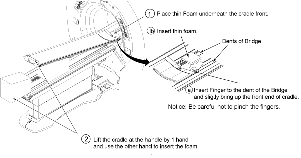
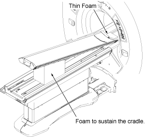
- Place the thin foam underneath the cradle front to prevent bridge and cradle from scratching.
- Lift the cradle at the handle by 1 hand and use the other hand
to insert the foam
Figure 2. Cradle Disassembly 3
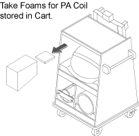
 note:
note:Foam is stored in the Card during installation.
Figure 3. Foam Storing Location
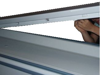
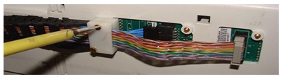
- Access to the Connectors below the Cradle.
Figure 4. Cradle Disassembly 3
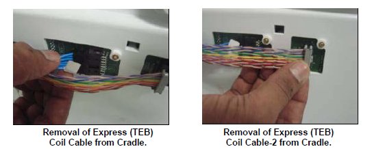
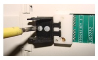
- Remove RF & DC connector from the socket mounted on the
cradle:
Figure 5. Cradle Disassembly 4
-
If there is no cable clamp: Remove
two M3 screw with the help of flat screwdriver and remove cable track
fixed on the cradle.
Figure 6. Cradle Disassembly 5
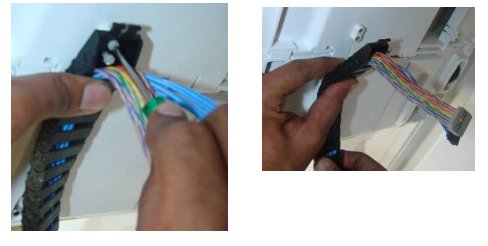
-
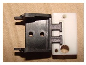
If there is cable clamp: Remove two
M3 screw with the help of flat screwdriver and remove cable track
and Clamp Top fixed on the cradle:
Figure 7. Cable Clamp
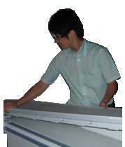
- Now cradle is independent of Table top.
- Lift the cradle and place cradle on flat surface.
Figure 8. Lift the cradle
 |
2 Cradle Assembly procedure:
Procedure
- Verify that the pad is still on the Table.
- Lift the new cradle and put it back onto the Table.
Figure 9. Cradle Assembly 1
- notice
- Replacement procedure for Revised RF Cable, DC Cable and DC
Cable clamp assy.
Get below mentioned FRU part as per replacement requirement
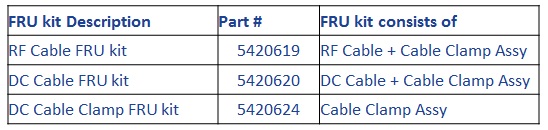
Figure 10. RF Cable FRU kit
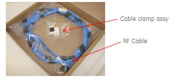
Figure 11. DC Cable FRU kit
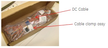
Figure 12. DC Cable Clamp FRU kit
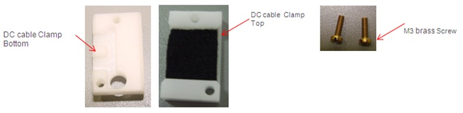
- Assemble DC cable Clamp bottom to Cable track end link.
Figure 13. Assembly DC Cable clamp
- Fasten these parts to cradle section with M3 screw.
Figure 14. Fasten DC Cable clamp
- Connect RF Cable and DC cable to cradle board, ensure both
the cable are placed flat one over the other.
Figure 15. Connect RF Cable and DC Cable to cradle board
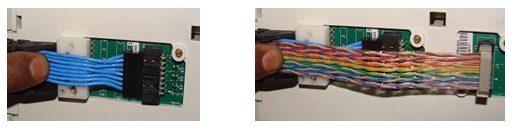
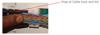
- Snap the Cable track along with RF Cable and DC cable to Cable
track end link.
Figure 16. Snap the cable track
- Assemble DC cable Clamp top to DC cable Clamp bottom with M3
screw.
Figure 17. Assemble DC Cable clamp
- notice
- Remove Foam and restore the Cradle position.
- In case if cradle is interfering or not locking with table top Side guide, for adjustment refer to Cradle Guide Rail Latch Adjustment .
- Restore Foam to the Cart.
- Paste PA coil identification label , refer to PA coil identification label Replacement procedure
|
|
3 Finalization
Procedure
- Turn On the System Power. Refer to Lockout / Tagout for System Cabinet PDU Main Breaker.
- Perform Express Coil MCQA Test .