ECG Leads Checks
Prerequisites
All the of the ECG clip leads are connected together. The right leg (RL) lead supplies a +2.5Vdc drive signal to the right arm (RA), left arm (LA), and left leg (LL) leads. The signal from each of these leads is read and checked to ensure that their respective inputs to the ECG A/D converter are in the +2.5V ± 200mv range. If any of them are not in this range, an error message is entered in the message log. If the signals from the RA, LA, and LL leads are all out of range, it is assumed that the RL lead has failed.
Procedure
- Remove right middle side cover and right front side covers.
- notice
Side Middle Cover (Right side Only)
-
Side Covers (Right front side Only)

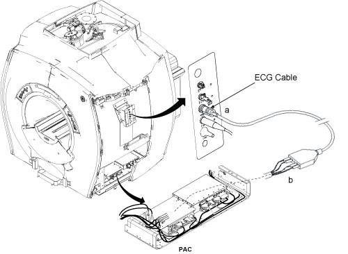
- Connect the cardiac gating lead to the Physical Acquisition
Controller (PAC) Assembly as shown in Figure 1.
Connect the clip leads to the test points on the PAC (the test points
are all shorted together). The clips leads are color-coded: Red is
LL, White is RA, Black is LA, and Green is RL.
Figure 1. PAC ASSEMBLY WITH ECG LEADS CONNECTED
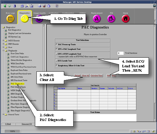
- Refer to Figure 2 for starting ECG
Lead Test.
Figure 2. Starting PAC Diagnostics
- The test takes about 30 seconds. If any lead fails, an error message indicating the faulty lead is reported in the Test Results Screen.
- Click on Stop to exit the Diagnostics window. The TPS will reset upon exit.
Finalization
- Restore Magnet Enclosure.
- Put the system back in patient scanning condition.
- Do a check scan to insure the system is operating properly.