Dock cover Assy
Prerequisites
Procedure
- Turn the system power OFF. Refer to Lockout / Tagout for System Cabinet PDU Main Breaker.
- Remove FRP bottom covers of Fixed Table.
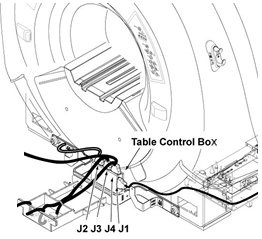
- Remove dock cover assy by 2 screws, Disconnect the Foot switch
Cable from the Control box.
Figure 1.
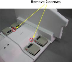
- Fix the new dock cover assy by connecting Foot switch Cable
from the Control box and installing 2 screws
Figure 2.
- Fix the FRP bottom covers to the table.
Finalization
- Turn the system power ON. Refer to Lockout / Tagout for System Cabinet PDU Main Breaker.
- Level the Table and perform Height Adjustment. Refer to LEVELING FIXED TABLE and TOP HEIGHT ADJUSTMENT.
- Fix the FRP Covers of the Table.
- Perform CRADLE HOME SENSOR CHECK .
- Check the Table Function. Refer to TABLE CHECKS AFTER INSTALLATION .
- Perform Express Coil MCQA Test to check that the PA coil cable is properly connected.