Cabinet Monitor
Prerequisites
Procedure
- Remove L Upper Front Cover. Refer to SC Cover Removal.
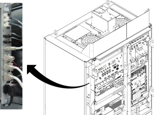
- Disconnect all connector from cabinet monitor. (J2, J3, J4,
J5, J10, J12, J13, J7, J8, J9, J14, LINE/FUSE)
Figure 1. Cable Disconnection from Cabinet Monitor
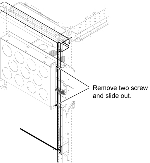
- Loosen 2 screws tightening cabinet monitor to the chassis.
Figure 2. Cabinet Monitor Removal
- Disconnect J11 (CAN terminator) from defective Cabinet Monitor and connect it to new Cabinet Monitor.
- Install cabinet monitor by the reverse order of the removal.
- Restore the System Cabinet.
1 Finalization
Procedure
- Restore the Power. Refer to System Cabinet PDU Main Breaker LOTO Procedure.
- Perform Cabinet Monitor Functional Check.
- Run one head or body scan.