Cabinet Monitor Functional Check
Prerequisites
1 Cabinet Monitor Functional Diagnostic
Procedure
- Run the Cabinet Monitor Functional Diagnostic.
- Open Common Service Desktop.
- Select 'Diagnostics / System Function / Peripheral Communications / Cabinet Monitor Functional Diagnostics'.
- Select 'Run'.
Figure 1. Cabinet Monitor Functional Diagnostic
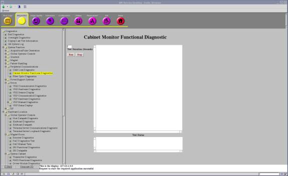
- Check the results. Table 2 shows the normal results.
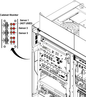
2 Leak Sensor Test
There are two Leak sensor routes. This test checks that the each sensor route does not contain broken wire.
-
Leak Sensor 2
-
HDsv Front Leak Sensor Assy 5332131 (Leak sensor 2-A 6613102)
-
HDsv Bottom Leak Sensor Assy 5334211 (Leak sensor 2-B 6613104, Leak Sensor 2-C 6613101, Leak Sensor 2-D 6613104-2)
-
HDsv Water Tray Leak Sensor1 5332992 (Leak sensor 2-E 6613105)
-
Leak Sensor 3
HDsv Water Tray Leak Sensor2 5332993 (Leak sensor 3 6613105-2)
This test also checks Sensor Fault LEDs (SF2, SF3) works correctly when disconnecting each sensor cables (Sensor 2, Sensor 3).
note:Required Condition: Cabinet Monitor Breaker is ON and Sensor Cables (Sensor2, Sensor3) are connected.
Procedure
- Check that the each Sensor Fault LEDs (SF2, SF3) is not blinking.
- Disconnect sensor 2-A and check that Sensor Fault LED (SF2) blinks. And the PDU is in stop mode.
- Turn OFF and turn ON the Cabinet Monitor switch to reset Cabinet
Monitor. Reconnect the sensor, press the EMO reset.note:
It is necessary to turn OFF and turn ON the Cabinet Monitor switch to reset Cabinet Monitor.
If one disconnected cable is found for Leak Sensor 2, the Sensor Fault LED2 blinks, error message is shown at OC. PDU is in stand by mode.
If one disconnected cable is found for Leak Sensor 3, the Sensor Fault LED3 blinks, error message is shown at OC.
- Repeat step 2 and step 3 for sensor 2-B,2-C,2-D, 2-E and sensor
3.
Figure 2. Leak Sensor Test
3 Finalization
Finalization
No finalization steps.