CAM Lite 3 Rear Boards
Prerequisites
Procedure
- Remove L Upper Front Cover and R Upper Front Cover. Refer to SC Cover Removal
- Disconnect the following connectors from front panel of CAM
Lite 3 and HUB.
-
Ethernet switch (HUB): port 6, port 7, port 8
-
IXG: J8, J11, J13
-
PSE: J7, J10, J11, J12, J13
-
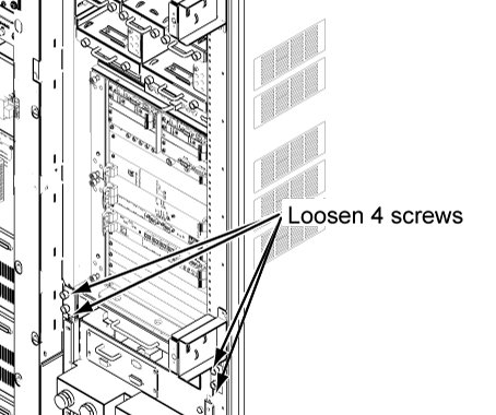
- Loosen 4 screws tightening bracket and chassis.
Figure 1. 4 screws
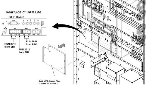
- To withdraw CAM Lite2 chassis, remove CAM Lite Access Plate
and check remove optical cables from PSE I/O Board.
Figure 2. opt cable removal
- Withdraw CAM Lite 3 Assy until it stops at stopper position.note:
When draw out the unit, be careful to cables and unit.
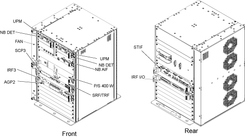
- Disconnect connectors from defective board of CAM Lite 3 rear
panel.
Figure 3. Board Location
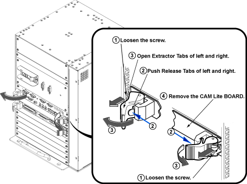
- Loosen 2(or 4) screws fixing board to the chassis.
- Push release tabs in the lever, and gently pull the extractor tabs located on the left and right of the circuit board.
- Slide the circuit board all the way out of the card cage, being
careful not to bend or bind the card in any way. note:
The circuit board should be handled using only the faceplate, ejectors, and the edges of the board.
Figure 4. Rear Board Removal
- Place the card in an appropriate shipping package, or discard, if applicable.
- Remove the packing material from the replacement board, and gently slide the circuit board along the slot guides into the chassis.
- Gently engage the circuit board connectors with the backplane. If it doesn’t feel like the circuit board is properly engaging the backplane, remove the board and check the connectors for bent or broken pins.
- Once the board ejectors contact the CAM Lite 3 chassis faceplate, gently push the ejectors in to the center of the board. This action will cause the ejectors to insert the board into the chassis. Do not attempt to use anything other than the ejectors to insert or remove the board from the chassis.
- Tighten the faceplate holding screws to secure the circuit board to the card rack. Caution: Do not over-tighten these screws.
- Reconnect the all connectors to board.
- Restore the system cabinet by reverse order of removal.
Finalization
- Restore the Power. Refer to System Cabinet PDU Main Breaker LOTO Procedure.
- Run MGD Diagnostics to ensure proper functionality.
- Run one head or body scan.