Actuator
Prerequisites
Procedure
 warning
- Ensure shut down PHPS and power to Megaswitch.
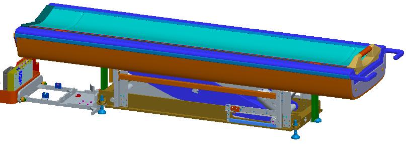
- Disassemble base covers, all scissor covers, rear support.
Figure 1. Disassemble base covers, all scissor covers, rear support
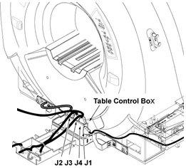
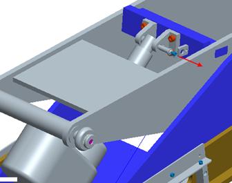
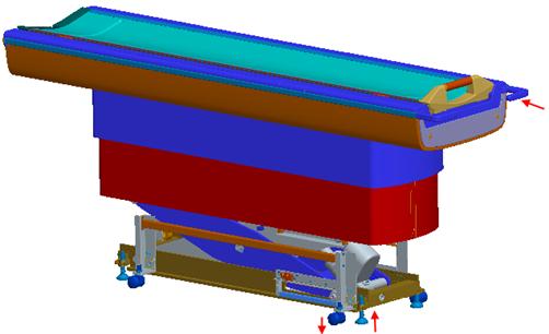
- Disconnect cables in dock frame area, disconnect table with
dock frame.
Figure 2. Disconnect cables in dock frame area, disconnet table with dock frame
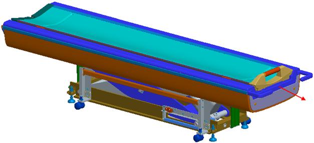
- Install casters, lower leveling pads if necessary, heighten
leveling pads after casters are installed. Move the table out of bay.
Figure 3. Install casters, lower leveling pads if necessary, heighten leveling pads after casters are installed. Move the table out of bay
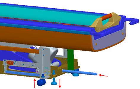
- Lower leveling pads to touch ground.
- Use screw rod to support.
Figure 4. Use screw rod to support
- First disconnect bottom actuator pin, then disconnect top pin.
Figure 5. Disconnect bottom actuator pin
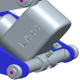
Figure 6. Disconnect top pin
- Use screw rod to move table to near mid position (propose to deliver actuator when half extended).
- First install bottom pin, then top pin.
Figure 7. Install bottom pin
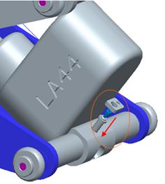
Figure 8. Install top pin

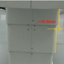
- Install mid scissor covers, then top scissor covers, ensure
min. 3mm gap.
Figure 9. Install mid scissor covers
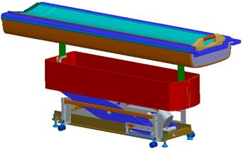
Figure 10. Install top scissor covers
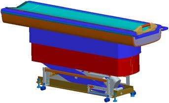
Figure 11. Ensure min. 3mm gap
- Heighten leveling pads, lower casters to topmost position, push
table back to bay.
Figure 12. Heighten leveling pads, lower casters to topmost position, push table back to bay
- Push table back Lower leveling pads, remove casters Align table height with magnet and level table by adjusting leveling pads.
- Tighten table with Dock frame and connect all cables.
- Install rear supporter.
- Install bottom scissor covers, ensure min. 3mm gap.
- Install base covers and caps Install dock cover.
- Shut up PHPS and power to Megaswitch.
 |
Finalization
- Turn the system power ON. Refer to Lockout / Tagout for System Cabinet PDU Main Breaker.
- Level the Table and perform Height Adjustment. Refer to LEVELING FIXED TABLE and TOP HEIGHT ADJUSTMENT.
- Fix the FRP Covers of the Table.
- Perform CRADLE HOME SENSOR CHECK .
- Check the Table Function. Refer to TABLE CHECKS AFTER INSTALLATION .
- Perform Express Coil MCQA Test to check that the PA coil cable is properly connected.