ASC-Lite Chassis Theory and Troubleshooting
1 Diagnostics
There are UPM Diagnostics that can be found on the Common Service Desktop. Details on these diagnostics can be found in Peripheral Diagnostics.
2 Reference Documents / Vendor Manuals
-
FRU Manual
-
Block Diagrams
3 LED Descriptions
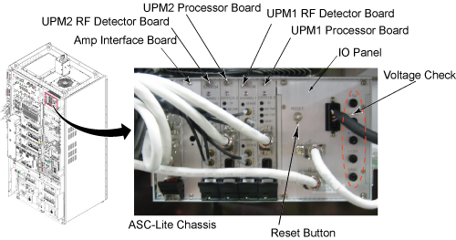
3.1 Input Panel
Connections to input power and CAN communication. ON/OFF switch for entire ASC-Lite Chassis. Reset Button will reset both UPMs; however, any measured RF power from the scanner is NOT reset. Voltage banana jacks are for checks of the power supply.
Figure 1. ASC Chassis Details
3.2 Power Supply
The power supply provides 3.3V, 5.0V, +12V and –12V to the UPM processor UPM detector boardsand RF interface baords.
3.3 Processor Board
The processor board for UPM1 and UPM2 are identical. These boards collect sample data from the detector boards, calculate the RF power and inhibit the scan if the trip limits have been exceeded or if some other UPM error occurs
3.4 RF Detector Boards
ASC-Lite has 2 RF detector boards. Each RF detector boards are identical. These boards convert measured RF power into a digital signal that is sent to the processor boards. Each board has two channels and each channel has 3 RF input ports, see details in the table below.
3.5 RF Interface Boards
This board permits the host to control and monitor the operation of the SRFD3. The board controls the Narrowband RF amp.
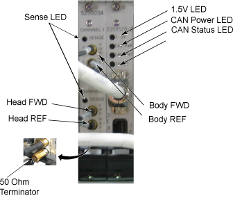
3.6 UPM1 / UPM2
Every system contains two (redundant) UPM’s. These UPM’s are identical and boards can be swapped between the two for troubleshooting; see UPM Board Swap Procedure for details.
A 50 Ohm Terminator is required on any RF port on the RF Detector Boards that is not being used.
Figure 2. UPM 1 Or UPM 2
4 UPM Calibration Troubleshooting
4.1 Theory
The UPM calibration runs a pcal scan and adjusts digital attenuators internal to the UPM to match the expected RF signal level.
The UPM calibration parameters found in the UPM calibration files are used in the calibration/functional check program. The program code sets the digital attenuators in the UPM based on the results of the 3 calibrations per channel (forward, reflected and hybrid reflected (if applicable)), and a comparison to these UPM calibration parameters. This calibration file is accessible from within the UPM calibration tool from the “File” pull down menu, “Edit Config” option.
The final UPM digital attenuator values are written to the UPM Calibration Configuration files (UpmCal1.cfg, UpmCal2.cfg) located in directory: w/config. There can be substantial variation in these calibration values from port to port, or on the same port following the replacement of any hardware.
Prior to starting the troubleshooting of the UPM, you can save the current calibration files as the Default backup. This can be done by entering the UPM calibration tool, selecting File and BKUP UPM Cal. After troubleshooting, if the UPM is restored in its original configuration (ie, each board is in its original location) you can restore the backup calibration file by opening the UPM calibration tool, selecting File and Restore BKUP UPM Cal. (The following error message may appear: "Warning: single selection listbox control requires that the Value be an integer range. Control will not be rendered until all of its parameter values are valid."….this error can be ignored)
4.2 Troubleshooting
If the UPM calibration fails, first check the system error log. Use the Problem/Solution Table in Section 7 to troubleshoot the errors in the error log. If Problem / Solution Table does not solve the calibration errors, attempt the following steps:
-
Quit UPM Calibration tool, end any open exams and TPS reset.
-
Open a new exam, Patient ID: geservice, weight: 111 lbs.
-
Select Service, Other.
-
Select apb cal (series 1 if t/s body and series 2 if t/s head).
-
Select Save Series.
-
Make sure that the correct hardware setup exists (ie cables connections and dummy load connections match setup in documentation).
-
Click on Manual Pre-scan.
-
Change TG to 200 if troubleshooting UPM Forward Power Calibration.
-
Click on Scan TR.
-
Check for inhibit light on ASC/UPM Chassis, Driver Module.
-
Check for Sense LED’s flashing on the correct channel (both RF Detector boards should have one of the channel’s Sense LEDs flashing, matching the Channel you are troubleshooting).
-
Stop MPS.
The system must be able to scan with the correct UPM Sense LEDs flashing prior to running the calibration. If the Sense LEDs are not flashing, check the error log to determine if the scan was stopped. Also check that the hardware setup is correct.
If setup and system are okay but the Sense lights are not flashing, make sure RF is getting to the UPM by placing a 50 Ohm terminator in the port you are troubleshooting and the UPM RF cable into a 50ohm terminated scope. Make sure you see a RF signal, if no signal exists, attempt reading at various points along the cable path to determine where the signal is lost. If a signal exists, attempt swapping/replacing RF Detector boards.
5 UPM Functional Check Troubleshooting
The UPM Functional check runs a prescribed scan in the RF Chain selected. It compares the measured RF power from the UPM to the expected value in a config file. If the values do not fall within 12%, then the functional check will fail.
In addition, the functional check confirms the UPM will stop scanning if the RF measured exceeds the trip limit
If the functional check fails to run, first check the system error log. Proceed toProblem / Solution Table for troubleshooting UPM system errors.
If the functional check fails due to inaccurate power measurement recalibrate the UPM then attempt the functional check again
6 Problem / Solution Table
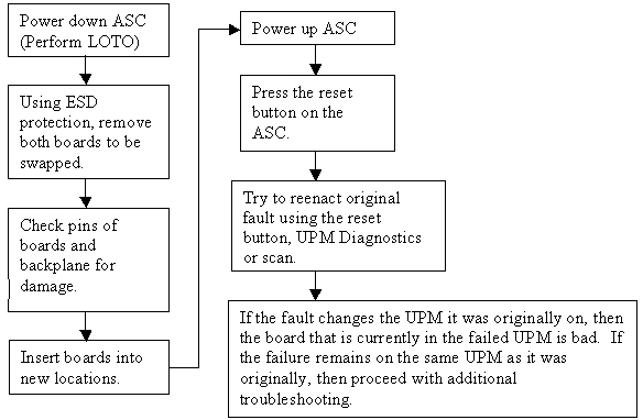
7 UPM Board Swap Procedure
UPM Board Swap Test
If either the Processor Board or RF Detector boards are swapped, the UPM calibration and functional check must be run prior to patient scanning.
Figure 3. UPM Board Swap Procedure