Universal Power Monitor - Head Setup and Calibration
Prerequisites
1 HEAD FORWARD POWER CALIBRATION
Procedure
- notice
- If Body UPM is NOT calibrated before Head UPM Calibration, reset
“UPM1Cal.cfg” and “UPM2Cal.cfg” file to 0
according to the following procedure.
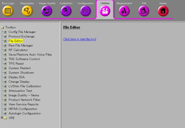
- Open File Editor by selecting Utility/File Editor from Common Service Desktop.
Figure 1. File Editor
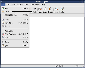
- Select File/Open.
Figure 2. File/Open
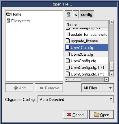
- Select 'w/config/Upm1Cal.cfg' and Open.
Figure 3. Select file
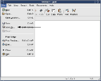
- Select Save As... and save the file as 'Upm1Cal.cfg.bk' .
Figure 4. Save As
- Select File/Open.
Figure 5. File/Open
- Select 'w/config/Upm1Cal.cfg' and Open.
Figure 6. Select file
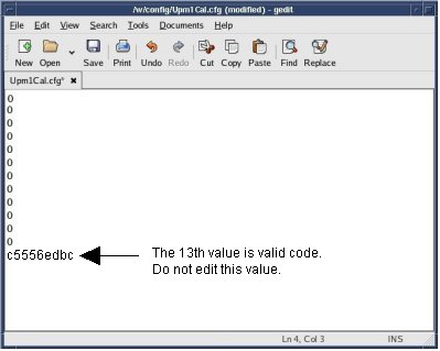
- Edit the file so that the 12 values are set to '0'.
Figure 7. Edit
- Save the config file.
Figure 8. Save

- Perform the same procedure for 'Upm2Cal.cfg'.
- Quit the tool.
- Perform [TPS Reset].
- Open File Editor by selecting Utility/File Editor from Common Service Desktop.
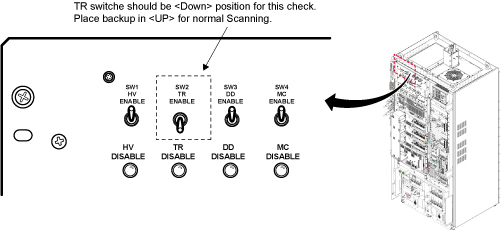
- Inhibit TR faults. The Driver Module in the System Cabinet, Figure 9. Move switch 2 to the TR Disable position.
Figure 9. Driver Module Front Switches
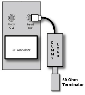
- Remove the head heliax able from J3 at the back of the RF Amplifier
and connect it directly to the RF dummy load. Figure 11.note:
If the Head RF power out procedure was just completed, configuration is the same. You can leave the Body RF heliax cable disconnected and the head output can keep the wattmeter in line. It will not change the outcome of the calibration.
note:7/16Male -N Female Adapter is located at System Cabinet Left Shelf. Remove left cover and find it. See Figure 10Figure 10. Built In Service Tool
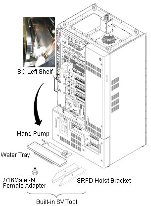
Figure 11. Setup for Head Output Measurement
 |
2 Setting up Software Tool to Calibrate UPM – Head Forward Power
Procedure
- To establish a Landmark, Start a New Exam.
- Enter the following parameters:
- Patient ID: geservice
- Weight: 111
- Withdraw the Cradle from its previous position.
- Place the head coil on the cradle and plug the coil connector.
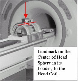
- Insert the Head Sphere and Loader into the Head coil as shown in Figure 12.
- Press Align on.
- Place the laser alignment light on the center of the Phantom
in the Head coil. Refer toFigure 12.
Figure 12. Landmarking the Head Coil
- Press Landmark
- Press Advance to Scan
- From the Common Service Desktop Select:
- Select Calibration Tab
- Select UPM Tool. Figure 13.
Figure 13. Starting UPM Tool
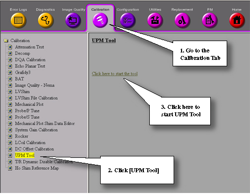
- Select Hyper Link to start UPM tool.
See Figure 14.
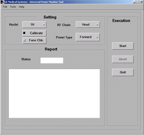
Figure 14. UPM Monitor Tool GUI
 note:
note:The first time running the UPM Calibration tool after a load from cold, the following Error may appear: “The spectroRFampType and upm.config do not match! Please run the UPM Tool config file editor and hit [Restore Defaults] and save the config file”. If this error appears, click [File] -> “Edit Config”. When the window opens, click [Restore Defaults] then close the screen. The tool will now have the correct information and this pop-up will not appear again during future UPM Calibrations.
- Select the Nuclei 1H.
- Select the RF Chain you are going to calibrate Head.
- Select Power Monitor type. Forward.
- Select: Calibrate Button
- Select Start button.
- Status should indicate Pass/Fail from 1 minute to 7.5 minutes depending on software version (tool should notify user of current step in progress). If Failure occurs, see Universal Power Monitor (UPM) Troubleshooting.
3 Finalization
Procedure
- Remove the cables and power measurement equipment.
- Reattach the Head and Body Heliax Cables.
- Re-enable T/R Drive. See Figure 9.
- Upon completion of any UPM calibration, Reset TPS. The system will not scan until this step is complete.