- id_13107121
- Version: 3.1
- Date: Oct 24, 2019 2:54:53 AM
T/R Quad Extremity Coil Replacements
Prerequisites
| Required persons | Preliminary requirements | Procedure | Finalization |
|---|---|---|---|
| 1 | Not Applicable | 30 minutes | Not Applicable |
| Item | Quantity | Effectivity | Part number | Manufacturer |
|---|---|---|---|---|
| Flat-head Screwdriver for No. 6 size screws | 1 | Cable Replacement | - | - |
| Flat-head Screwdriver for No. 4, 6 and 10 size screws | 1 | Mechanical Components | - | - |
| Digital Multimeter | 1 | Testing Cable Functionality | - | - |
| Loctite® 222 (12-month shelf life) | One 10 cc bottle | - |
46-170683P1 |
- |
Follow this procedure to replace field replaceable units on the T/R Knee/Foot Coil by Invivo.
Cable Functionality
Cable Continuity Check
Procedure
- notice
- Select the Ohmmeter function on the Digital
Multi-Meter (DMM).
Figure 1. HD System Connector (View from Cable End)
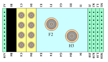
- Refer to the previous illustration. Using the DMM, verify continuity
of the cable by performing a continuity check on the system connector:
-
From A1 to A2 pins
-
From M9 to M10 pins
-
- Remove the six brass screws from the underside of the cable connector housing, and unplug the cable from the Printed Circuit Board (PCB).
- Access the reference points on the exposed interconnect PCB,
and perform continuity checks on the following reference points from
the PCB to the system connector block (Figure 1).
From To MC-1 C1 REF LOAD H3 TX F2 PA +10 VDC M3 MC BIAS J1 COIL ID M7 COIL ID RTN M8 - While checking, flex the cable to test for intermittent open
and short conditions within the cable.
-
If the cable fails any of the tests, contact GE Customer Service to order a new cable assembly.
-
If the cable passes the tests, plug the interconnect PCB back into the Preamp PCB, and secure the cable to the underside with six brass screws removed previously.
-
Cable Replacement
Procedure
- notice
- Remove the bottom screws from the extended housing.
Figure 2. Cable Replacement
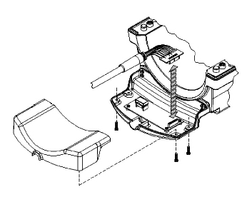
- Carefully remove the top cover and set it aside.
- Unseat the cable from the cradle, carefully remove the small PCB with the 20-pin connector from the large PCB, and set the cable assembly aside.
- Replace the cable assembly with the new one, mating the 20-pin connector in the socket.
- Seat the cable assembly into the cradle and replace the cover, ensuring the cable end sits level and upright.
- Replace and hand tighten the bottom screws in the cover.
- Scan the coil to ensure proper assembly.
Mechanical Parts Replacement
Mechanical Hardware Check
Procedure
- Lift the coil locks on both sides of the coil, and slide the coil from side to side. (The coil must slide freely back and forth on the base without binding or grinding.)
- Lock the coil in the center of the base, and check the bottom
of the base to ensure the four rubber feet are tight.note:
Make sure the coil latch is secure and the base lock is fastened.
Draw Latch Replacement
Procedure
- Remove the two 6-32 x 0.438 FHMS brass screws from the housing, and replace the draw latch with the new one.
- Use Loctite 222 on the brass screws, insert them into draw latch and hand tighten.
- Test the draw latch to ensure proper assembly.
Handle and Cover – Coil Lock Replacement
Procedure
- Mate the new handle and cover pieces together, and fasten with the 4-40 x 0.375 PHMS brass screws.
- With both handle locks in the upright position, pry one side of the handle lock from the cradle on the side of the housing, and slide the lock assembly from the T-Bracket.
- Use Loctite 222 on the brass screws, replace the lock assembly with the new one, and secure with the screws.
- Place one end of the lock assembly into the cradle of the housing, and maneuver the other side into the cradle.
- Test the lock mechanism to ensure proper assembly.
T-Bracket Replacement
Rubber Bumper Replacement
Procedure
- Remove the 6-32 x 0.50 PHMS brass screw from the rubber bumper.
- Replace the rubber bumper with the new one, and secure with the brass screw.
What to do next
Finalization
No finalization steps.