- id_2012346
- Version: 5.0
- Date: Aug 23, 2019 3:55:34 AM
Setting up for head only or both head and center scan
Procedure
- At the scanner, remove any surface or head coil from the bore. Confirm that the cradle is at the home position.
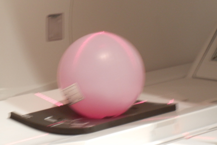
- If setting up for the head only scan, position the head sphere phantom as shown in the following illustration.
For GEM (flat) table:
- Place the pad toward the head of the table.
- Position the head sphere phantom on the pad.
For curved table:
- Install the service filler panels under each of the two cradle panels.
- Place the pad toward the head of the table.
- Position the head sphere phantom on the pad.
Figure 1. Positioning for head location (phantom and pad)
- From the home position, move the cradle in so that the in-room monitor shows 315 mm. Turn on the alignment lights by pressing the Alignment button on the magnet enclosure.
Figure 2. Buttons on magnet enclosure
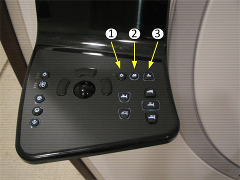
Item Description 1 Alignment lights button 2 Landmark button 3 Advance to scan button - Adjust the head phantom location where the laser light cross hairs line up on the center of the phantom. Press the Landmark button.
- If scanning only the head location, press Advance to scan. Proceed toAccessing dual drive quadrature tool.
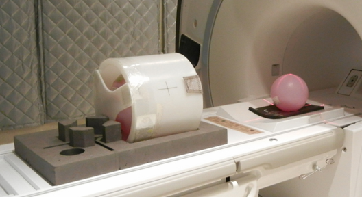
- If scanning both head and center locations, move the cradle in an additional 765 mm.Align the body loader and sphere on the center of the laser light cross hairs. Press Advance to scan, and proceed to Accessing dual drive quadrature tool.
Figure 3. Positioning for center location (body loader and phantom)

- notice