- id_13107089
- Version: 3.0
- Date: Aug 29, 2019 1:57:06 AM
1.5T Phased Array Shoulder Coil Cable Replacement
Prerequisites
| Required persons | Preliminary requirements | Procedure | Finalization |
|---|---|---|---|
| 1 | Not Applicable | 30 minutes | Not Applicable |
| Item | Quantity | Effectivity | Part number | Manufacturer |
|---|---|---|---|---|
| Flat-blade Screwdriver | 1 | - | - | - |
| Item | Quantity | Effectivity | Part number | Manufacturer |
|---|---|---|---|---|
| 1.5T HD Shoulder Cable (DVw) | 1 | Coil P/N 5344905 |
5344456 |
SFO, India |
Procedure
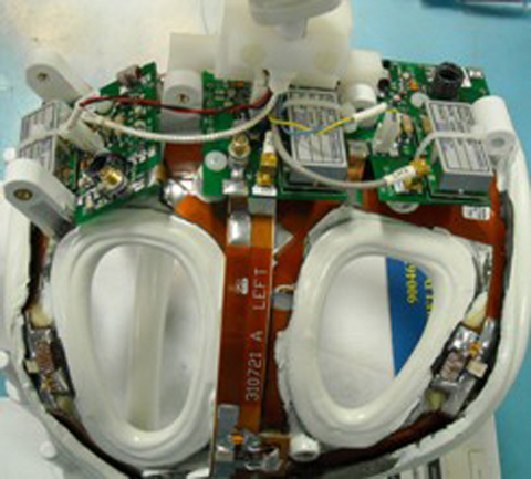
- Remove the coil covers by taking out the screws located in the covers (six on the right side, three on the left).
- Remove the cover from the shoulder coil as shown.
Figure 1. Shoulder Coil with Cover Removed (P/N 5344905)
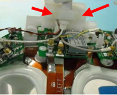
- Remove the two screws (shown below) that hold the cable clamp
in position. (Cable is captured beneath.)
Figure 2. Cable Clamp Screws (P/N 5344905)
- Remove the three PCX connectors for RF & DC connectors located on the feed boards for Chl 1, Ch 2 and Ch 3.
- Remove the cable assembly from the coil.
- To install the new cable assembly, connect the BRN-WHT DC connector and Ch 2 RF PCX connectors before the Cable Clamp is attached and the screws are tightened. To install the clamp use the two screws removed earlier.
- Connect the PCX and DC connectors to appropriate feed boards: Clear RF and RED-BLK DC connectors to Ch 1 and GRY RF and BLU-YEL DC to Ch 3. (Ch 2 RF and DC connection already completed in previous step.)
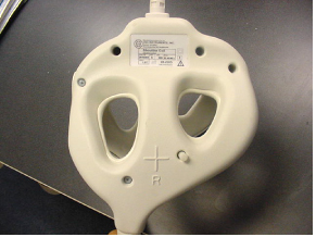
- Install the covers and replace the screws removed earlier. Make
sure to capture the strain relief inside of the covers.
Figure 3. Coil Cover Reinstalled
Finalization
No finalization steps.