- id_13106797
- Version: 3.0
- Date: Aug 29, 2019 1:53:09 AM
1.5T NV Array Cable Replacement
Prerequisites
| Required persons | Preliminary requirements | Procedure | Finalization |
|---|---|---|---|
| 1 | - | 30 minutes | - |
| Item | Quantity | Effectivity | Part number | Manufacturer |
|---|---|---|---|---|
| 5117092-3: 1.5T NV Array Cable | 1 | - | - | - |
Follow this process to replace the cable assembly on the 1.5T Neurovascular Array by Medrad (M3087JJ).
Procedure
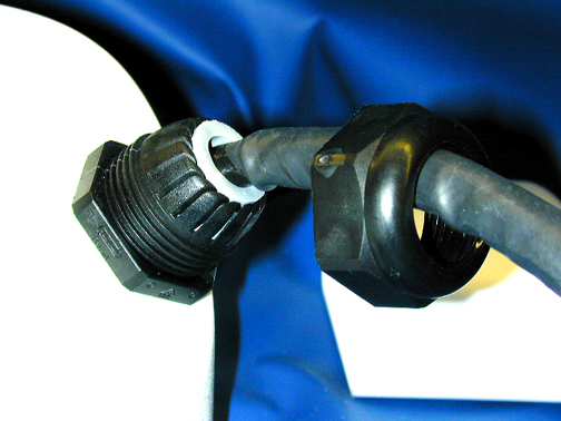
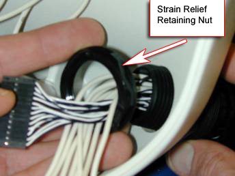
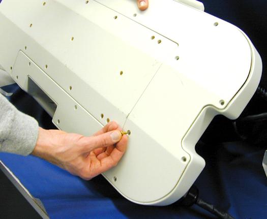
- Loosen the cable Strain relief retaining nut from the external
cable. See Figure 1.
Figure 1. External Cable's Retaining Nut Location
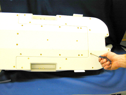
- Lay the NVA HD on its side and remove the 14 screws holding
the base cover on the unit as shown in Figure 2.
Figure 2. Location of Screws on Base Cover
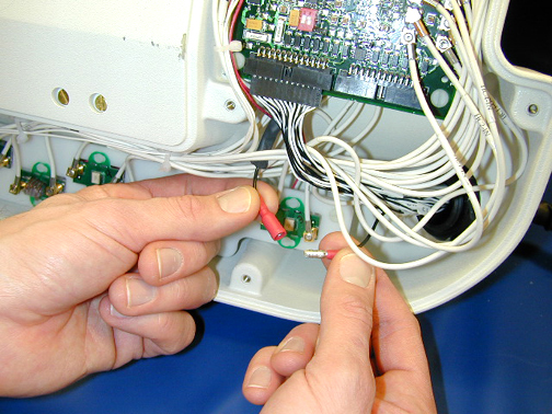
- Disconnect the cable shield lug from the system shield wire
as shown in Figure 3.
Figure 3. Disconnecting the Cable Shield Lug
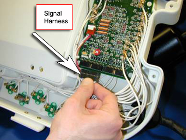
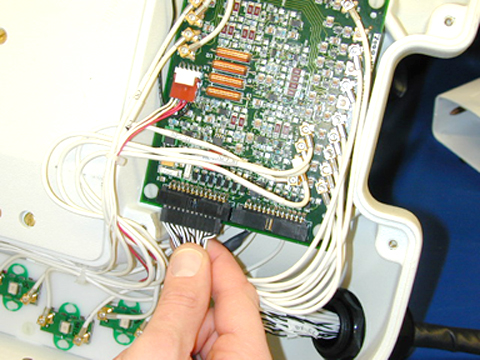
- Disconnect the signal harness from the multiplexer board. See Figure 4.
Figure 4. Location of Signal Harness
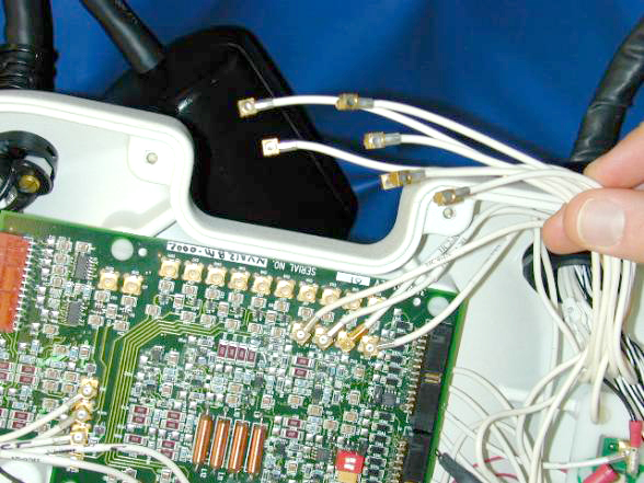
- Disconnect the coax cables from the multiplexer board. See Figure 5.
Figure 5. Disconnecting Coax Cables
- Remove the strain relief retaining nut and remove it from the
cable assembly. See Figure 6.
Figure 6. Removing the Strain Relief Retaining Nut
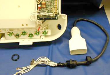
- Remove the cables and strain relief from the base of the NVA
HD. See Figure 7.
Figure 7. Removing Cables and Strain Relief from the Base
- Remove the strain relief seal ring from the body of the strain
relief. See Figure 8.
Figure 8. Removing the Strain Relief Seal Ring
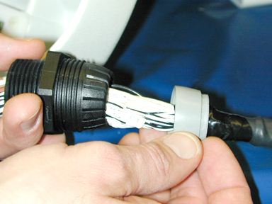
- Remove the coax cables from the body of the strain relief followed
by the signal wires. See Figure 9.
Figure 9. Removing Strain Relief from Cable
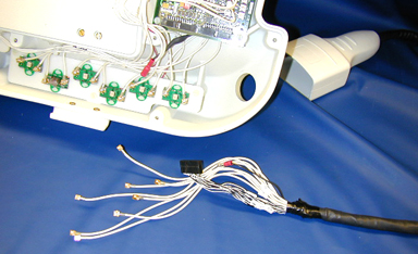
- Remove the strain relief seal and the strain relief-retaining nut from the cable. See Figure 9.
- Slide the strain relief-retaining nut over the replacement cable
followed by the strain relief seal, and then the strain relief body.
See Figure 10.
Figure 10. Putting the Strain Relief Parts on the Replacement Cable
- Insert the cable assembly beginning with the signal wire connector
followed by the coax cables through the NVA base. Slide the cable-retaining
nut over the cables and secure as shown in Figure 11.
Figure 11. Attaching Cable to the NVA Base
- Connect the corresponding coax cables to the multiplexer board.
See Figure 12.note:
The cables are marked for proper placement.
Wire Color Channel White 1 White/Black 2 White/Red 3 White/Green 4 White/Orange 5 White/Blue 6 White/Brown 7 White/Yellow 8 Figure 12. Connecting the Coax Cables
- Connect the signal harness connector to P2 of the Base Mux.
See Figure 13.
Figure 13. Connecting Cable Harness
- Connect the cable shield lug to the system shield wire as shown
in Figure 14.
Figure 14. Connecting the Cable Shield Lug
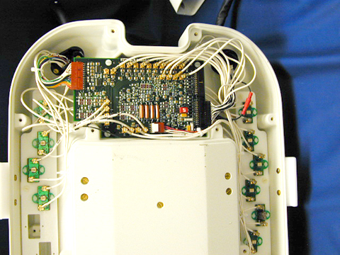
- The final assembly should look like the image shown in Figure 15.
Figure 15. Final Assembly
- Tighten the cable strain relief retaining nut to the external
cable. See Figure 16.
Figure 16. Securing the External Cable
- Replace the base cover and the 14 retaining screws. See Figure 17.
Figure 17. Replacing the Base Cover
Finalization
No finalization steps.