- id_13106799
- Version: 3.0
- Date: Aug 29, 2019 1:57:16 AM
1.5T 8 CH Body Coil Cable Replacement
Prerequisites
| Required persons | Preliminary requirements | Procedure | Finalization |
|---|---|---|---|
| 1 | Not Applicable | 30 minutes | Not Applicable |
| Item | Quantity | Effectivity | Part number | Manufacturer |
|---|---|---|---|---|
| Standard Tool Set | 1 | - | - | - |
| Item | Quantity | Effectivity | Part number | Manufacturer |
|---|---|---|---|---|
| Cable Assembly | 1 | - |
2417162 |
- |
This procedure will replace the cable assembly on the 1.5T HD 8CH Body Array Coil (P/N: 2415366) by GE/USAI, Catalog Number M3335MC.
Procedure
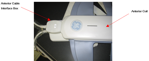
- Unplug the Anterior Cable Interface Box (Labeled with UP) from
the Anterior Body Array Coil as shown in Figure 1.
Figure 1. Removal of Anterior Cable Interface
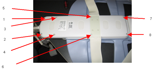
- Remove all the 8 screws form the lower Posterior Coil cover
as shown in Figure 2. Remove the cover after removing
the screws.
Figure 2. Removal of 8 Screws from Posterior Coil
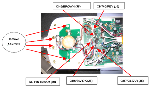
- Remove all the four screws as shown in Fig 3 below; Unplug the
RF cables labeled with CH5-CH8 and DC PIN Header Connector carefully
as shown in the Figure 3.
Figure 3. Posterior Coil RF Cable and DC Wire Removal
- Remove the cable from the Posterior Coil completely.
- Take the new 8 Ch Body array cable assembly and connect the posterior cable assembly into the Posterior Coil side as shown in Figure 3.
- Connect the RF Cables (J5-J8) and DC PIN Header connector into
the Body Array Coil Feed board PCB as shown in Fig 3 as per Table 4
Table 4 Posterior Cable Connection S.N Cable Designator PCB Designator 1 CH5/BROWN J8 2 CH6/BLACK J11 3 CH7/GREY J5 4 CH8/CLEAR J13 5 DC PIN Header J9 - Apply all the four screws and tighten them as shown in Figure 3.
- Place the Lower Posterior Coil Cover on the coil and tighten all the screws (8) as shown in Figure 2.
- Plug the Anterior Cable Interface Box (Labeled with UP) of the new cable assembly into the Anterior Coil as shown in Figure 1.
Finalization
No finalization steps.