- id_13107028
- Version: 3.0
- Date: Aug 29, 2019 1:52:50 AM
1.5T GP Flex Coil Introduction
Product Identification and Shipping List
The coil consists of one major assembly shown below.
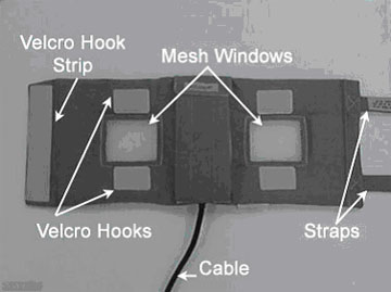
Figure 1. 1.5T GP Flex Coil
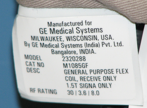
To identify the 1.5T GP Flex coil, refer to the coil label.
Figure 2. 1.5T GP Flex Coil Label
The unit is 55.6 cm long (not including straps) by 22 cm wide with two mesh windows that indicate the open center of the two coils and aid in positioning. Two 78.5 cm long straps are attached to one end of the coil fabric. The underside of these straps are covered with Velcro, which attach to a Velcro hook strip at the other end of the coil and to four Velcro hooks located above and below the mesh windows. A 183.3 cm long RF cable exits the material on one of the long sides and has a BNC connection that attaches to the Surface Coil Adapter.
| Description | GE Part Number | Quantity |
| 1.5T GP Flex Coil | 2320288 | 1 |
| Operator Manual | 2336151-299 | 1 |
Environmental Requirements
Storage Requirements: Store the coil in the scanner room.
Dimensions:
-
55.6 cm x 22 cm x 4 cm, excluding cable assembly
-
78.5 cm strap length
Weight: 575 grams (approximately 1.268 lbs) maximum
Theory of Operation
The General Purpose (GP) Flex Coil design is a linear, receive-only flexible coil. The GP Flex Coil consists of two loops that are serially connected to create a co-rotating saddle coil pair. When aligned properly, this saddle design provides exceptional uniformity across the sensitive volume of the coil and a minimum of bright spots or high-intensity areas. If the loops are positioned in a more open fashion (i.e., moved farther away from each other, toward a planar or flat configuration), the image uniformity decreases.
Be aware of the following:
-
For close positioning, do not overlap the coil ends. Doing so will not damage the coil, but the performance will suffer.
-
For optimal positioning, the circular shape should be maintained with the two mesh windows 10 cm apart and the coil ends 5 cm apart. Some deviation from the optimal position will not significantly degrade the uniformity. This coil can be used in anatomical areas such as the hip, brachial plexus, larger knees and ankle.
The coil consists of one major assembly shown in Figure 1). The two loops are in a flexible material covered with fabric that allows the GP Flex Coil to bend in one direction, making it easy to wrap around the anatomy of interest.
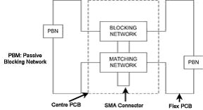
The Functional Block Diagram of the antenna electronics is shown in Figure 3. The two flex PCB wings on either side of the rigid PCB form the loops. The rigid PCB has a matching network that matches the loaded antenna to 50 ohms and an active blocking network. The blocking network consists of a single PIN diode and a tuned LC network. The diode is forward biased whenever the body coil transmits. The external cable is connected to the antenna via a right angle SMA jack. The flex PCB has passive blocking networks that consist of a Schottky Diode and a tuned LC network.
Figure 3. GP Flex Coil Functional Block Diagram
Coil Care
 |
|

|
|
Special Care Requirements (If Applicable)
Contact the GE authorized Service Personnel for coil disposal at the end of product life.