
- 00000018WIA30E69F20GYZ
- id_131065593.0
- Feb 23, 2021 3:25:49 AM
Receive chain theory
Disclaimer
Systems using DV26.0 software or later will use either the RRx receive chain or the DPP receive chain. To determine receive chain type, check the Receiver Type field in the Hardware Configure tab of Guided Install. RRx indicates the RRx receive chain, and DPP indicates the Digitize Per Pin (DPP) receive chain.
Overview
The receive chain takes the low-level analog signal from the MR coils and digitizes it for reconstruction to create an image. Coil ports are connected to the receive electronics through cable tracks which carry RF and coil communications. In systems equipped with the RF hub architecture, the RF cables are connected to the RF switchboards which provide gain control. The signal then goes through a mixer module, where the proton frequency is downconverted to a ~16 MHz Intermediate Frequency. The signal is then output from the mixer module as a differential signal to the remote receiver (RRx). The RRx and DPP receiver work in a similar manner, digitizing and then decimating and filtering the data. The digital data is sent through a SFP fiber optic transceiver to either the iVRF within the ICE chassis or to the VRF board within the VRE chassis. The iVRF/VRF does more digital filtering, adjusts the R2 gain stage, and hands the data off to VRE. The VRE then reconstructs the data into an image and transfers it via Ethernet to the GOC, where it is displayed on the operator monitor.
Safety
| Warning | |
|---|---|
| Notice | |
|---|---|
| Notice | |
|---|---|
Block diagrams
-
Systems with CAM and RRx (16 and 32 channel)
Figure 1. CAM and RRx receive chain (16 and 32 channel) 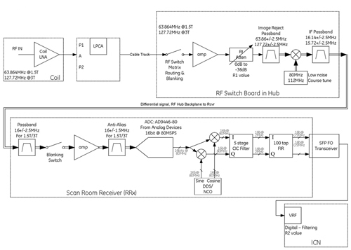
-
Systems with ICE and RRx (32 channel)
Figure 2. ICE and RRx receive chain (32 channel) 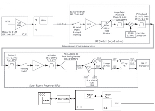
-
Systems with ICE and DPP (96 or 128 channel)
Figure 3. ICE and DPP receive chain (96 or 128 channel) 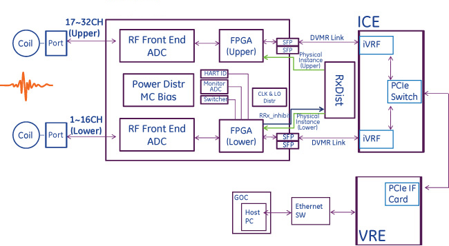
Hardware features
RF switchboard (RFSB)
16-channel systems use one RFSB, while 32-channel systems use two.
The RFSB board’s main function is to route and down convert up to 96 input MR signals to 16-channel IF receivers. The RFSB interfaces to MR coils through the coil interface ports and a gain stage. Once the signals reach the RFSB, they are routed according to system configuration, and subsequently down-converted to the desired Intermediate Frequency. Finally, the signals are routed to 16-channel IF receivers.
-
Routes contiguous banks of four input signals from 16W16 RF connectors to a contiguous group of four available IF receivers. The banks of contiguous signals is defined starting with the first connector pin as (1,2, 3, 4), (5, 6, 7, 8), and so on.
-
Gains and down converts MR RF signal to differential IF frequency signal.
-
Combines each MC bias from MC driver boards to the RF input connector center pin.
-
Provides signal loopback path required for receive chain diagnostics.
-
Switches input away from the signal channel during the transmit cycle to protect the receive hardware.
-
Monitors RRx status for real-time error messaging and diagnostics.
Remote receiver (RRx)
The remote receiver’s (RRx) main function is to provide analog and digital signal processing and A/D conversion for 16 channels of data.
-
16–bit analog-to-digial conversion
-
Digitial decimation and filtering
-
Communications to/from RF hub
-
Control of TDM module and notching of data
DPP receiver
DPP where the analog signal is converted into digital signal, decimated, and filtered.
-
DPP receive chain treats two set of 16ch block
-
Each 16ch has independent physical instance assigned by RxDist but HART ID is the common
-
Lower 16ch FPGA is master FPGA for error handling and communication with RxDist as follows
-
Read HART ID, board revision
-
Monitor ADC
-
Switcher frequency setting
-
Send RRx inhibit to RxDist
-
ICE module
For ICE module information, see ICE Theory.
MC bias board
The multi-coil driver board (MCDB) is to provide DC bias for protecting sensitive receive circuitry from high RF power during transmit and to couple RF signals during receive. Receive coils contain decoupling circuitry which require DC bias to control PIN diode circuits in the multi-coil arrays to achieve this functionality.
16-channel systems use one MCDB board. 32-channel systems use two.
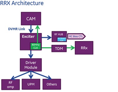
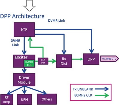
Tx UNBLANK and clock distribution
Tx UNBLANK: In DPP architecture, DPP modules receive Tx UB command directly through DVMRlink from ICE/SCP. In RRx architecture, NB exciter receives Tx UB command from SCP and RF HUB receives Tx UB through copper link from exciters.
Clock: In DPP architecture, both RxDist and DPP RRx P Ports operates by 80MHz CLK. In RRx architecture, RRx operates by 80MHz ClockK though RF HUB operates by on-board oscillator.
Power distribution for DPP receive chain
Receive single DV22V power from DCPS and RxDist distributes the power to receiver of each port module. On-board power is regulated individually.
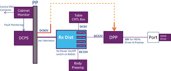
| Voltage/current | 22 V +1V/-10%, 45.5A (max) : 13.5*3+5 A |
| Interface | 24W7 connector |
| Monitoring | Cable detect only and no 1-wire communication. Power monitoring is done in cabinet monitor. |
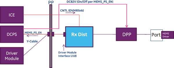
MEMS control
Disclaimer:
Software version DV29.1 and later introduces support for a non-MEMS system configuration. Existing or upgraded systems will continue to use the MEMS power supply. Newly installed or upgraded systems may not have the MEMS power supply. Identify the presence or absence of MEMS on your system by looking for the MEMS DC Power Supply Assembly (part number 6859128) in the power supply rack of the ISC.
Micro Electro-Mechanical Switches (MEMS) that support ultra-fast coil switching is controlled as follows.
-
82V MEMS Power is turned off when scan is not performed.
-
KPA and P ports support MEMS.
-
Control signal of 82V Power supply is provided from RxDist to DCPS for MEMS.
Inhibit concept
-
RxDist and DPP P-ports identify fault conditions (Apex Module, CLK loss, DVlink, and so on) and inhibit RF.
-
DPP P-port FPGA gathers fault condition and sent to RxDist, then, RxDist provides Master Inhibit line to Driver Module to indicate fault of Rx Chain.
-
Identify inhibit sources which impact on functional loss (incl. power fault) and coil protection.
-
All the fault condition are transferred to ICE through DVMRlink – Recognized by error message on UI.

| Inhibit Source | RRx P Port | Rx Dist | Category |
| Apex Module Fault (MC Bias) | x | Coil Protection | |
| Coil Present | x | Coil Protection | |
| Internal Coil Fault (Legacy BTE) | x | Coil Protection (MEMS Driver) | |
| Invalid LUT Index for SOTF | x | Coil Protection | |
| Loss of CLK | x | x | Function Loss |
| Loss of LO | x | x | Function Loss |
| Loss of DVMR Link | x | x | Function Loss |
| Loss of Power Good | x | x | Function Loss |
| Loss of SFP Good | x | x | Function Loss |
| Cable detect from inhibit cable | x | Function Loss | |
| Cable detect (others) | x | x | Function Loss |
Related documents
For more information see: