
- 00000018WIA30B3ED20GYZ
- id_131071643.0
- Aug 29, 2019 1:53:03 AM
1.5T GP Flex Coil Replacements
Simple removals that are clearly obvious are not described here. Unless otherwise noted, the steps for re-assembly are simply the reverse order of the steps described for disassembly.
Personnel Requirements
| Required Persons | Procedure Timing |
| 1 | 30 minutes |
Overview
Follow this process to replace components of the 1.5T GP Flex Coil (M1085GF).
Preliminary Requirements
Tools and Test Equipment
Standard Tool Kit
Replacement Parts
-
Cable Kit (2337313)
-
Hardware Kit (2337313-2)
-
1.5T GP Flex Coil (2320288)
-
(For MR450) 1.5T Single-Channel Adapter (5176411)
-
(For EXCITE) 1.5T Single-Channel Adapter (2383623)
-
(For HDx & HDxt) 1.5T Single-Channel Adapter (5140888)
Procedure
Disassembly/Assembly of Coil
Unless otherwise noted, the steps for reassembly are the reverse order of the steps described for disassembly.
-
For disassembly, refer to the illustration below.
Figure 1. Coil Disassembly 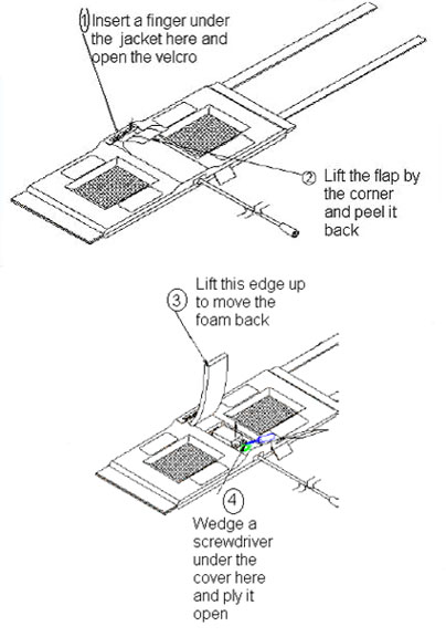
-
To reassemble:
-
Replace the cover on the posts and press on it till it snaps into place.
-
Push the foam flap under the jacket.
-
Carefully replace the fabric flap making sure that the Velcro® on the edges lines up with the Velcro on the jacket.
-
Tuck the end of the flap under the jacket, and press over the Velcro while making sure that no edges are left open.
-
External Cable Replacement
-
Disassemble the coil by referring to Figure 1. Unscrew the two nylon screws and remove the strain relief upper cover.
Notice -
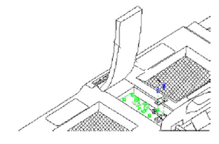
Using two 8 mm wrenches (one on the circuit board female connector and one on the male cable connector), unscrew and remove the male SMA cable connector from the circuit board.
-
Remove the external cable from the coil as shown below.
-
Install the new cable.
-
Stabilize the circuit board and the connector on the circuit board.
-
Tighten until snug, but do not overtighten; too much torque (>2 kgf-cm) can result in damage.
-
-
Replace the strain relief, and reassemble the coil per 2
Mechanical Hardware Replacement
-
Refer to Replacement Parts for the FRU list.
-
To replace the cover assembly, refer to Disassembly/Assembly of Coil.
-
To replace the upper strain relief block and the two screws, refer to External Cable Replacement.
-
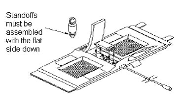
If a plastic standoff breaks, it can be removed using needle-nose pliers. Insert a new standoff in its place while making sure that the flat end goes in first as shown below.
Finalization
Perform 1.5T GP Flex Coil SNR Test.